With African Mohogany purchased from Armstrong Millworks in Highland Michigan and Okoume plywood purchased at Public Lumber in Detroit, the frame build got started. The same layout board was used as an assembly jig. Blocks were screwed down to locate frame members so that epoxy gluing, screwing and or nailing could be done while maintaining alignments.
Tampilkan postingan dengan label frames. Tampilkan semua postingan
Building the templates for the frames
Diposting oleh ghone | 0 komentar | 20.09Label: boat making, Building, for, frames, templates, the
Fairing the Frames and Longitudinals
Diposting oleh ghone | 0 komentar | 00.11Label: and, boat making, fairing, frames, longitudinals, the
The process of beveling and smoothing all the surfaces that the plywood "skin" mates to is called fairing. It is inherently a bit confusing to the new boat builder as its hard to know where to start, what tools to use, and how much material to remove.
The picture shows the tools I ended up using from top to bottom in the picture: 1) power 3 1/4" hand planer, 2) small belt sander Porter-Cable 2 1/2"X 14", 3) 1" Stanley hand plane, 4) 8" Jack plane, 5) Rasp, 6) Disston Abrader, 7) Long sander (made from 1/4" scrap wood to fit a 3x21 belt from a belt sander).
After filing some notches at the frames to set the angle of the longitudinal pieces, the major wood removal starts to blend the shapes from one spot to the next along the longitudinal pieces. I found the power planer a bit aggressive and hard to see what was happening until after a pass was made. The hand planes turned out to be quite effective at removing material quickly on the curved surfaces. They were a pleasure to use since they are quiet and they allow the surface to be seen as you work which is reassuring . The small Porter-Cable power sander was a great tool as the vacuum pick-up removed the dust effectively and it was fairly easy to see what was being removed. It was great for putting the contour on the frames. 
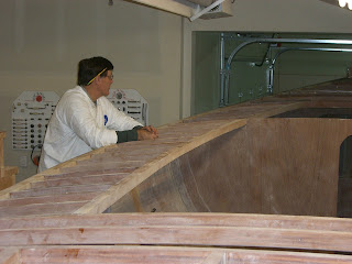
The bottom piece on the right side of this picture is called the shear. It has not been faired yet and is still a square section. The idea is to angle it so the outer surface points towards the member above it (the chine). The trick is that the angle is constantly changing and it turned out that my chine surface was not sufficiently angled to have a prayer of getting a piece of plywood to lay on it and the shear at the same time. So the chine had a couple more laminations of material added to get the bottom angled out enough to "point" towards the shear below it.
In this picture, the bottom piece (shear) is faired so that its surface points toward the chine above. This area of the boat probably took the most time as quite a bit of wood needed to be removed. You can see a lot of plane shavings and dust on the floor.
I think Im done with fairing, but it seems to be a task that could be done to infinity because with every new look it appears that a surface could be sweetened a little more. I think its good enough to move on and Ill fix something if I see the need as I prepare the plywood planking pieces.
All Frames Standing!
Diposting oleh ghone | 0 komentar | 04.42Label: all, boat making, frames, standing
Excitement at the boat shop today... |
Here Im tightening the last bolt on the last frame that needed to be installed! |
Done! Shes framed. Cold beer ensued. |
Ramon sawing out those chine notches like a champ. |
View from the "inside" |
The little trailer looks like a superheroine with a big, flowy cape during the dust storm that followed the boat shop success. This photo was taken about an hour and a half before sunset. |
Dust. This was taken about an hour before sunset. And then, it rained. Hallelujah. |
The frames are built
Diposting oleh ghone | 0 komentar | 01.08Label: are, boat making, built, frames, the
During early November 2009, frame construction took place. Frame pictures show surfaces that have been encapsulated with clear epoxy and sanded to receive subsequent coats or gluing. While plans call for nailing of gussets, I used a couple of drywall screws at each gusset to prelocate parts so glue up would repeat the dry fit. One side was done at a time and let set over night. Then the frames were flipped, and reset into blocks and the second set of gussets were located and screwed, then disassembled, glued, screwed, and nailed. The flipping of the parts indicated the accuracy of the initial tracing of frame halves. In some cases, in minor tweaks of the assembly blocks were required. At final glue-up, silicone-bronze screws were used to replace any drywall screws used for pre-fit. Pre-drilling was required on the nails as the Okoume plywood is very dense and the mohogany frame pieces showed a slight split on the first gusset installation if nailed near an edge without pre-drilling.
Starting the third year by mounting the deck frames
Diposting oleh ghone | 0 komentar | 06.48Label: Boat Plans, by, deck, frames, mounting, starting, the, third, year
January 2011 was the beginning of the third year of the build. With meticulous records Richard has totalled 2693 hours. He originally calculated 5 to 6 thousand hours to completion....about the half way point?
By subtracting out the 13 weeks lost to building due to injuries and other obligations, but not removing other short times off to see the kids, travel to boat festivals, etc he has averaged 30 hours per week on the boat. Sometimes he works as much as 60 hours per week, especially at times like preparing for the boat rolling.

View of the saloon bulkhead that will be raised to cabin height.

Glassed in subfloor over the integral water tanks.

Glassed and sanded main bilge area with the engine compartment visible in front of picture.

Support framing for the deck and the back lazarette was created at the transom. The sheer was notched and frame pieces mounted to the transom to hold the quarter knees.

After fitting, the quarter-knees, frames and brackets were sanded, finished with epoxy and prepped for mounting.

The brackets between the quarter-knees frame out the lazarette.

The bracket is cut up to allow access into the sides.

Back frames are added to support the hatch.

All frames are epoxied in place and clamped.

Clamps at every angle.

Richard has been being diligent about wearing his "sperm suit" and respirator while doing epoxy work. He started to develop a burn type rash on the inside of his lower arms while using
epoxy in short sleeves. Sanding partially cured epoxy also seemed to increase the irritation. So back to full coverage.

The cockpit was constructed from 3/4" marine plywood. Since creating a smooth nice fillet on the inside corner was a challenge, Richard trimmed and used a piece of cove moulding. The floor of the cockpit will be glassed and epoxied seperately. The rabbet around the bottom of the well will increase the epoxy surface and the floor will be be screwed into place with bronze screws.

A compact cockpit, but since she has a tiller, there will be no binnacle to hog floor space.

A nice view of the frames in place. The center is the cockpit, the left and back are lazarettes.

I couldnt resist another pic of the sweet transom.....

I tried another view, but it is pretty distorted.

More finish epoxy work, fillets, and sanding of the entire inside.

The entire inside is sanded and cleaned.

This is looking into the port side lazarette.

Now....to start fairing the deck frames......lots of arm breaking work to get the tops of the frames smooth in relation to each other.
Read More..
By subtracting out the 13 weeks lost to building due to injuries and other obligations, but not removing other short times off to see the kids, travel to boat festivals, etc he has averaged 30 hours per week on the boat. Sometimes he works as much as 60 hours per week, especially at times like preparing for the boat rolling.
View of the saloon bulkhead that will be raised to cabin height.
Glassed in subfloor over the integral water tanks.
Glassed and sanded main bilge area with the engine compartment visible in front of picture.
Support framing for the deck and the back lazarette was created at the transom. The sheer was notched and frame pieces mounted to the transom to hold the quarter knees.
After fitting, the quarter-knees, frames and brackets were sanded, finished with epoxy and prepped for mounting.
The brackets between the quarter-knees frame out the lazarette.
The bracket is cut up to allow access into the sides.
Back frames are added to support the hatch.
All frames are epoxied in place and clamped.
Clamps at every angle.
Richard has been being diligent about wearing his "sperm suit" and respirator while doing epoxy work. He started to develop a burn type rash on the inside of his lower arms while using
epoxy in short sleeves. Sanding partially cured epoxy also seemed to increase the irritation. So back to full coverage.
The cockpit was constructed from 3/4" marine plywood. Since creating a smooth nice fillet on the inside corner was a challenge, Richard trimmed and used a piece of cove moulding. The floor of the cockpit will be glassed and epoxied seperately. The rabbet around the bottom of the well will increase the epoxy surface and the floor will be be screwed into place with bronze screws.
A compact cockpit, but since she has a tiller, there will be no binnacle to hog floor space.
A nice view of the frames in place. The center is the cockpit, the left and back are lazarettes.
I couldnt resist another pic of the sweet transom.....
I tried another view, but it is pretty distorted.
More finish epoxy work, fillets, and sanding of the entire inside.
The entire inside is sanded and cleaned.
This is looking into the port side lazarette.
Now....to start fairing the deck frames......lots of arm breaking work to get the tops of the frames smooth in relation to each other.
Aligning Frames and Laying the Keel
Diposting oleh ghone | 0 komentar | 16.18Label: aligning, and, boat making, frames, keel, laying, the
After the confirmation that this boat will make it out of the basement, I secured my frame pieces to the leveled form rails. After checking a hundred times if things were square to each other, I aligned the stem using a string and plumb bob method. I tried a laser but it was better at confirming the set-up than actually doing it.
I used steel carriage bolts for the dry run set up of the keel and transom knee. When I was satisfied with alignments I took the keel and transom knee apart and did the glue-up. When all was, glued, bolted and screwed in place I called it a day. The next day I sighted down the keel and saw hump between frame #1 (middle frame and frame #2 (front frame), which wasnt a real issue, but there was a dip between the transom and frame #1 which was a problem. The picture is sighting down the keel from the front and the flash didnt illuminate the keel after the middle frame. After sleeping on it, I decided to try and realign the transom a bit to straighten the keel forward of the transom.
I decided to shim frame #1 rearward about 1/16" and this gave me some room between the transom and form to re-align it. I pulled a 1/16" shim out to lower the transom, added one at the top of the form angle to the transom and this allowed clamping of the transom near the bottom of the form and I could dial out the dip in the keel with a twist of the clamps. So with the keel flat from transom forward to frame #1, I could move on.
Langganan:
Postingan (Atom)