Tampilkan postingan dengan label and. Tampilkan semua postingan

Alarmed And Connected

| 0 komentar |
I have now installed the alarm system.  Its a wireless setup which can take up to 16 sensors.  Currenlty I have 4 door break sensors and 4 passive PIR and a smoke detector.  The company is also devoloping a flood sensor which will be handy for the bilges and can be added to the system.


 This is the kit  As you can see it does a lot of clever stuff especially the GSM facilities.
Also installed is the 3G wireless router with exteral 9dBi aerial.  I hadnt planned on this when I put the lounge wall up.  I was rather chuffed with myself that I managed to find and dill into the 2" cavity from outside on the roof on the first attempt.  Once this was done it was simple a case of tracing the wire down.


See here for the full spec and Here for the aerial

Both of these devices will run directly from the 12v supply and draw a tiny amount of power.  The modem will only be on when we are at the boat, the alarm of course will be on all the time.  Standby draw is 0.5a
Read More..

Fairing the Frames and Longitudinals

| 0 komentar |


The process of beveling and smoothing all the surfaces that the plywood "skin" mates to is called fairing. It is inherently a bit confusing to the new boat builder as its hard to know where to start, what tools to use, and how much material to remove.


The picture shows the tools I ended up using from top to bottom in the picture: 1) power 3 1/4" hand planer, 2) small belt sander Porter-Cable 2 1/2"X 14", 3) 1" Stanley hand plane, 4) 8" Jack plane, 5) Rasp, 6) Disston Abrader, 7) Long sander (made from 1/4" scrap wood to fit a 3x21 belt from a belt sander).

After filing some notches at the frames to set the angle of the longitudinal pieces, the major wood removal starts to blend the shapes from one spot to the next along the longitudinal pieces. I found the power planer a bit aggressive and hard to see what was happening until after a pass was made. The hand planes turned out to be quite effective at removing material quickly on the curved surfaces. They were a pleasure to use since they are quiet and they allow the surface to be seen as you work which is reassuring . The small Porter-Cable power sander was a great tool as the vacuum pick-up removed the dust effectively and it was fairly easy to see what was being removed. It was great for putting the contour on the frames.


The bottom piece on the right side of this picture is called the shear. It has not been faired yet and is still a square section. The idea is to angle it so the outer surface points towards the member above it (the chine). The trick is that the angle is constantly changing and it turned out that my chine surface was not sufficiently angled to have a prayer of getting a piece of plywood to lay on it and the shear at the same time. So the chine had a couple more laminations of material added to get the bottom angled out enough to "point" towards the shear below it.

In this picture, the bottom piece (shear) is faired so that its surface points toward the chine above. This area of the boat probably took the most time as quite a bit of wood needed to be removed. You can see a lot of plane shavings and dust on the floor.
I think Im done with fairing, but it seems to be a task that could be done to infinity because with every new look it appears that a surface could be sweetened a little more. I think its good enough to move on and Ill fix something if I see the need as I prepare the plywood planking pieces.
Read More..

Some Tips and Things Leaned along the way

| 0 komentar |


Raising the bar: So far Ive been happy that I raised the form that the boat frames mount to. The plan says 24" off the floor, but I raised it to 32". With this small boat, I have not found it to be too high. The working level for the sides was good as I could sit on a stool for much of the work and it kept me off my knees. It is easy to get underneath the boat for various checks and bottom installation.


Recycled Ping-Pong Table: This has been a could base for mounting the forms while covering the carpet. Surrounded by 1/4" plywood, it does not move around and is a stable platform. If I had it to do over, I would add a 2x4 reinforcement from side to side directly underneath the form feet. It rocks slightly when pushed from the side as I only have a 2x4 reinforcement down the middle of the tables underneath where the 2x6 mounts down the middle. With the carpet and padding underneath the protective plywood, it flexes a bit underneath my feet and is very comfortable to stand on, unlike cement floors.


Gum Containers: I looked at an empty Eclipse gum container and being a pack rat it looked too good to throw out. So I asked myself, "Self, What could you use this for?" And the self answered, "Screws". They are terrific. The top unscrews for loading, the clear top allows seeing whats inside, it opens as a shaker spout for or the clear top pops open. Way cool. Im chewing alot of gum now trying to get enough containers for all the different screw sizes. Maybe they should advertise that!


Screw Lube: Sometimes screwing goes better with a little lube...get your mind back on track, were talking boats here. After breaking a couple of the silicon-brass screws, I started putting a small amount of "Screw-lube" on the tip and the problem went away.


Dry Wall Screws: I used these screws for the temporary screw blocks and while they may be cheap and drive home easily, but they also sometimes break when removed. I didnt learn my lesson and kept using them, and had another three break off when removing the screw blocks on the second front bottom piece.
Broken Screw Removal: When the cheap drywall screws are broken off at the surface with nothing to put a vice grip on, what do you do? They have to come out or they would rust later. After digging through my shop, I found a roll pin with an I.D. about the screw shaft diameter. I filed a short spiral so it would cut the wood around the screw shaft when rotated counter-clockwise. I chucked it up and started pushing and boring around the screw shaft. It would smoke and act like it wasnt going to work until with a bit more brute force it would grab the screw and out it would come. Drilling clockwise into scrap wood would remove the screw shaft so I could reuse it. I used it more than I would have liked.
Read More..

California Drought and Flood

| 0 komentar |

This is yet another California drought post, this one featuring a book by two women who know what they are talking about, that is, the climate of California since the last ice age.
The idea behind studying the earths past climate is that we might be able to see patterns that could help us predict climate in the future.  Unfortunately, climate is capricious and the best that climate studies can do is to give us a smorgasbord of options.  Our options for California are periods of benign climate interspersed with droughts and floods.  California has been in a benign, wetter than usual period for about 150 years.  That period may now be ending.  The entire culture and economy of present day California has been built on top of the expectation that the past 150 years are whats normal for the climate of California.  Sure there isnt enough water in southern California to support large scale agriculture and cities, but with dams and aqueducts, water has been brought from elsewhere to make life in southern California possible.  Northern California fares a little better than the south but cities in Central California, like those that rim San Francisco bay have to import their water from out of the area.
The truth of the situation is that California does not have enough water to support a population of 39 million people indefinitely.  It has enough water if the climate is sufficiently wet.  But it isnt always.  There have been droughts that have lasted for 500 years, from AD 900 to AD 1400 for instance, much longer than California has existed as a state. The present culture of California could not exist in such a climate. Indian cultures have existed in all these varying climates but they were never as dense as the present population.  They were also not as settled and had a better sense of climate variability than the people who built the present day California.
For example, the Central Valley of California where some large part of the produce sold in the US is grown floods periodically.  The Indians tended not to build permanent settlements there.  They moved there when floods were not imminent and moved to higher ground when storms were likely.  The current culture on the other hand has built cities and farms in this flood plain that gets flooded in excess of ten feet every hundred years or so. The last great flood happened in 1862.  A flood of this magnitude happening today would destroy a good deal of housing and farms and also displace 6 million people.  It would also very likely drown much of the infrastructure that brings water to Los Angeles, San Francisco and other coastal cities.
So perhaps drought is not even the worst threat to California.  Drought is a threat to agriculture in California but then agriculture in California was never a good idea unless one is comfortable with the idea that it might only be a temporary arrangement.
Read More..

Leaf Blowers and Entropy

| 0 komentar |
The other day, the gardeners were in our neighbors back yard and blowing away at the leaves.  As they usually do, they try to corral the leaves in one corner of the yard where they can then scoop them up and haul them off somewhere.  Unfortunately, when they blow them up against the fence that separates them from our yard, a good deal of the leaves and other debris ends up in our yard.  So yes, I am one of those people that thinks that leaf blowers are a bad idea.
But that is not my main point here.  My point is to talk about a definition of entropy that sees it as a degree of disorder.  In this view, entropy is created when the world becomes more disordered.  The gardener with the leaf blower lowers the entropy in his clients back yard but increases the overall entropy of the neighborhood by expending energy to create more order in a specific place at the cost of the larger environment.
This is how living organisms operate as well.  They hold entropy at bay internally by increasing overall entropy in their environment.  And it is only by holding entropy at bay by sucking energy out of their environment that living organisms can stay alive.
Still, it would be good if gardeners could work out a better way to remove leaves than by leafblowing and still put food on their table.
Read More..

A frame goes up and an auspicious arthropod goes down

| 0 komentar |
Frame 5 is the first to go up!
Floor 5 was situated about a quarter of an inch too far aft. One solution (and probably the proper solution) would be to replace the floor. I just shaved a quarter inch off of the timber real quick with a Skillsaw and chisel. Ramon was my hero in making it plumb with the plane when I got too frustrated to continue.

Treating bare wood with copper napthenate preservative.


And shes up! Three 3/8" bolts on each side. All wood-to-wood contact surfaces were soaked with copper and bedded in tar.


The "X" bracing and the cross beams at the sheer and just below the chine are temporary bracing.

Not the neatest job, but shes strong and deadly to fungi.

The first frame went up last night after a bit of a boat hiatus. Some coaxing with a Skillsaw and chisel got the frame to where it was supposed to hit the rabbet. Its nearly plumb, too. I apparently did a horrible job installing the floors, as three or four of them are not plumb nor flush with the station lines drawn on the keel. Ill be spending a lot of time over the next few days correcting my mistakes with a plane. This part of the boat building process has become tense as I anticipate bending a batten around the chine for the first time. I hope Luna will be beautiful.

Lucky for me, the universe sent me an auspicious sign this morning to calm my nerves.

I woke up at about 4 am this morning to a smelly, wet substance on my arm. I flung on the lights and, without my glasses, saw a blurry yellow puddle with a long, black swirly piece of business on my sheets where my arm had been. My mind immediately thought rats!, as I do have a history of sleeping in places were rats attack me in the night. Given this, and the series of rabies shots that followed, I am deathly afraid of rodents. I decided that, judging from the size of the mess on my bed, this rat had to be HUGE.  I frantically called Ramon to come over.

When I went back into my bedroom the turd was gone! I decided the rat must have come back and eaten it. I freaked. I had a monstrous, shit-eating rat in  my bedroom. I noticed a dark blurry mass moving slowly toward the corner of my bed. Rather than get closer, I decided to get out of there and start doing internet searches for, "feces consumption in rats," worried that there was a correlation between this behavior and rabies. Very productive.

When Ramon arrived, bleary-eyed and sweet as could be, we searched my bedroom with no luck. Ramon suggested the turd was in fact a culebrilla and that there was no rat. I was somewhat comforted by this possibility.

Culebrilla-- apparently common in the Valley, though sightings are rare.
But still-- the smelly yellow stuff made no sense. I resorted to Googling things like, "fat worm smelly yellow liquid" and finally came up with this:
A giant millipede! When stressed or injured, they secrete a pungent yellow substance that contains hydrogen cyanide. We never did find it, and these things live for 5-10 years. There was a lot of yellow stuff though, so one can hope it was fatally wounded. Ah well. Despite the long-lived monster spewing cyanide in my bedroom, I did sleep a little sounder knowing it wasnt a rat. 

The the silver lining in this early-morning fiasco? Apparently millipedes are good luck. Perhaps the chine will be fair after all.
Read More..

One Lives And Learns!

| 0 komentar |
I have to admit that despite doing all the calculations, in the real world the 240v electric combo microwave / oven just wasnt doing what it should have.

It did work from the engine alternators or the new 12v genset through the inverter but it was just not efficient and also an engine had to be running to use it so noisy too. So reluctantly I have had to admit          I was wrong.  I know I was told many times on the forums and had quizzical raise eyebrows from people I spoke to about it face to face.

So I now have a gas oven and full width grill and jolly well (and silently) it works too.


Once fitted I did a gas leak check with a digital manometer.  Start pressure was 39mb.  The supply was turned off and the pressure dropped to 30mb by turning on a gas ring.  It was left to settle for 5 minutes where it dropped 4mb.  After another 5 minutes the pressure had risen slightly to 28mb.  I left it another 20 minutes or so which is more than is required and the pressure remained at 28mb.  Test passed.


Read More..

Battens Cut and Fit

| 0 komentar |


My battens have now been ripped and fit to the frames. I had to deepen the pre-cut notches to get the battens to lay flush with the frame contours. Per the "Boatbuilding with Plywood" book, battens should be installed after side planking, so I used some steel screws for temporary dry fit so they can be removed if in the way for subsequent work. They helped secure the frames in position so Ill leave them in place if possible.


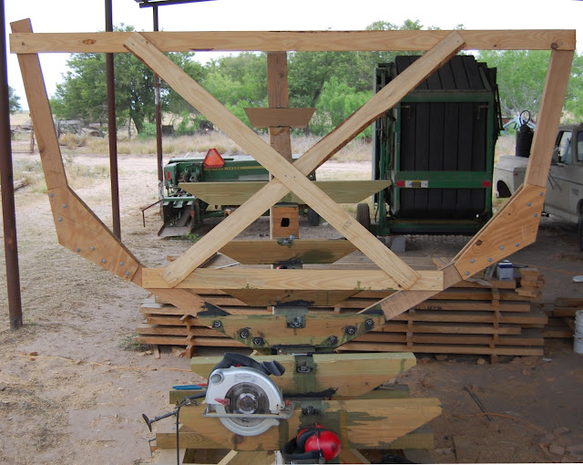
The sides of the middle frame were unsupported and could easily be pushed out of plumb so I added a temporary cross beam and some angle braces from it to the form to stablize them. Now they can be worked on without moving around.


The next step is fitting the chines. You can see in the photo that Im experimenting with a piece of pine to judge whether my notches are right. Im letting my buddy Ted forge ahead with his Zip and of course he just tried steaming his chines and installing and broke one. Im taking a vacation so the boat will be on hold for awhile. Maybe when I get back, Ted will tell me how to install a chine without making expensive mohogany firewood.
Read More..

A Dory for Gazela Primeiro and at the end tips on glass application

| 0 komentar |
A while ago I received a nice email from Tony Souza regarding construction issues with a new dory he intended building for the old Portuguese barkentine Gazela Primeiro.

Hello Ross,
Thanks for your recent article "Stems and Trailers".  In that article you discuss natural timber vs plywood construction and show the merits of plywood glued lapstrake for boats that are dry stored.
Im trying to choose a construction technique to use for a reproduction dory that will be "dry sailed".  The dory is a Grand Banks dory of 17 feet overall, 13 feet on the floor. The new dory has to resemble closely the last of the three dozen Portuguese grand banks dories that sat on the deck of Gazela Primeiro, the 100+ year old Portuguese barkentine on which I am one of the all volunteer crew.  Last winter we patched and repaired the last dory, and this year Id like to build a dory to be used often for the teaching of boat handling, rowing, and dory sailing.  the boat handling includes launching and retrieving over the side using hand operated boatfalls. The new dory will spend most of its time stacked inside the old dory, the two as deck displays of what was used in long line fishing of the early 20th century.
As a matter of resemblance the new dory will have four frame sisters overlapped, removable thwarts, 5/8" cedar planking, solid gunwales, a mast step on the floor and two sets of oarlocks.
For ease of construction and in keeping with the dry storage idea I plan on using modern materials where I can.  The flat bottom will be Meranti plywood already on hand, no need to soak the floor seams closed before putting boat into the water.  The frames are already built from laminated ash. Tree crotch and buttress sections are too difficult to find.  I plan to epoxy the garboard plank to the bottom, glass tape and epoxy the inside seam.  After planking I plan to turn the boat over and glass the bottom and garboard with cloth.
After that long prologue we come to my uncertainty area, the clinker planking joints.  Its tempting to use lap-stitch aka ship lap joints, easily cut with a router and epoxy fastened.  On natural, i.e. not plywood, timber that may lead to splitting along the grain at the join.  Likewise dory lapped (rolling bevel) joints likewise glued might suffer splitting.  I should have said earlier that using modern glues and eliminating metal fastners is a goal.  The old dory is a pincushion of steel nails on the planking joints which has resulted in rusty streaks and rotten wood.  (Of course dories were not supposed to last more than a couple years in ocean service. Old dory is probably 40+ years old.) 
Would it be better to caulk the planking seams with Boat Life, a polysulfide, rather than epoxy fasten?  The frames are there to give cross grain strength.  With your expeience you might see that Im headed for problems not yet envisioned.
Any suggestions will be very welcome and gratefully accepted.
Gazela can be seen at
www.gazela.org.
A picture of the old dory is attached. 


Here is part of the text of my reply: -

I agree totally with your concerns regarding "hard" gluing of either "lapstitch" or dory-lap joints when using natural timber rather than plywood - I believe that they would definitely crack at the point where the planking thickness returned to single-plank. Harry Bryan wrote about the matter when he did a couple of articles for WoodebBoat Magazine about the building of his Daisy design. She had either double-planked cedar (glued with epoxy) for the bottom, or a single sheet of plywood. The topsides were planked with lapstrake cedar planks in the normal manner (I think using copper clench nailing from memory). The important thing in our context is that he expected her to be dry-sailed, and after completing the planking in the normal way, he dragged a sharp, flat-blade screw driver along the underside of the lap on the outer side of the planking. This produced a sort of square-shaped groove of about 1/8" x 1/8" in the underside of the lap. He then filled the groove with a bead of polyurethane (I would use 3M 5200 or Sikaflex 292, using a polyurethane-specific primer)

Having said all that, I wonder whether you could just glue the entire lap with polyurethane (I dont know enough about polysulfide to say anything about its adhesive qualities where no fastenings are used). The polyurethane is strong enough, but I dont know whether a fully-glued lap would allow enough movement to overcome the cracking problem, even given the flexibility of the compound - but my guess is that it would be ok, especially if the glue-line was thick.

If I was doing it, Id go the copper-fastened route, with the polyurethane (or polysulphide) run into the groove under the lap.

I think that the garboard arrangement you propose would be fine. The glass on the outer face should supply cross-grain reinforcement, and the tape on the inside will extend some distance beyond the vulnerable line of intersection between the inside faces of the bottom and the garboard.

On two boats I built (one of which ended up in the Jody Foster film, Nims Island - see the recent comment made on Duckworks http://www.duckworksmagazine.com/10/reports/may/index.htm ), I made the bottom from Western Red Cedar glued strip, continuing around the turn of bilge, after which I continued the planking as plywood glued lapstrake. I cut the bevel on the bottom planking to accept the first lapstrake plank before glassing the bottom. When glassing the bottom, I continued the glass right around and onto the bevelled face. This meant that when the first plywood plank was glued on, the glass was sandwiched between the WRC strip planking and the inner face of the plywood - the aim being to prevent splitting in the WRC.  This explanation is a bit clumsy, but I havent got time right now to do a sketch. In your case this will not be necessary, as you will have the glass on the outside of the cedar planking anyway.

??
Western Red Cedar bottom planking
???
Bottom covered with 400gsm (12oz) double-bias glass and the first two planks of plywood lapstrake attached - the first plank going over the glass, which itself had been laid over the bevelled edge of the cedar bottom planking.
???Here is Tonys latest up-date: -

Hiya Ross,
Here are three pix of the dory project to date.  This boat is a copy of the last original belonging to Portuguese fishing barkentine Gazela Primeiro.  You can see more pictures on
www.Gazela.org and my facebook page. My version of the dory has a meranti plywood bottom and white cedar planking over laminated ash frames.  The gunwale and cap are white oak. The dory will essentially be dry sailed i.e. living on Gazelas deck most of the time and occasionally be used for crew training and exhibition at home and ports of call.
After corresponding with you some time ago I took your advice and epoxy joined only the garboard plank to the bottom.  The rest of the construction has followed traditional methods. The upper edge of the garboard and the remaining planks are dory lapped and copper riveted.  Planks to frames are joined with Si bronze screws.
I think we talked about covering the bottom and up to the upper edge of the garboard with synthetic cloth and epoxy. 
Now areas where I could use advice:
What cloth would be appropriate? I dont think the dory will ever see a beach, but it might. So a light cloth should do.
Is there an advantage to graphite additive to the epoxy?
Any tricks to applying the cloth?
Thanks for your help,
Tony Souza


And part of my reply: -

Dear Tony,

Thanks very much indeed for the up-date, and for the nice photos. The boat looks super to my eyes, and Id love to take her out in the rough stuff - preferrebly with some weight in the bottom to represent the ballasting effect of a load of Cod!

My appologies for the delayed reply - we have been recovering from the devastating flash-flood which wiped us out on January 10, and priorities tend to be re-arranged!

For the cloth, the simplest would be 200gsm (6oz) woven glass. This is light and easy to use, and gives a good level of protection, and more importantly, provides a sort of screed to ensure an even thickness of epoxy. Dynel is also a good option (4oz, I think, but you would need to check with the supplier). Dynel is bulkier than glass for the same weight, and it has superior abrasion resistance - I like it on decks - but it doesnt have the tensile stiffness of glass so it will have less structural effect on the garboard-to-bottom joint. For a hefty boat like yours which may get handled roughly, Id give serious thought to using 400gsm (12oz) double-bias glass cloth. It isnt woven, so it takes bends fairly well, and with the fibres aligned 45 degrees/45 degrees, every fibre crosses the longitudinal joints. It is cheaper than woven glass, but is heavier than the normal 6oz stuff.

I normally use the dry application method (for weights up to 12oz). I lay the cloth over the dry, sanded, and vacuumed surface, and them smooth it into position with a dustpan brush or a wide, dry paintbrush. Tape any troublesome edges down with temporary bits of masking tape. Then start by mixing small quantities of epoxy and pour them onto the glass (or Dynel) and spread them with a squeegee - I use rectangles of 1/16" model aircraft balsa as they can be bent along the grain if required, and the corners dont snag on the glass.  Dont press too hard, as you will end up aerating the epoxy and making it go creamy with minute air bubbles (just like what happens when whipping cream). Just use a gentle figure-eight sweeping motion to get it out onto the surface. Dont fuss about getting it to wet-out - that will happen automatically. Keep on mixing, pouring and spreading until the entire surface is covered. Small batches are good, as they dont heat up so rapidly in the container.

When the surface is covered, use disposable brushes and/or disposable foam rollers with about a 1/8" nap to distribute the resin evenly. I use dry brushes and rollers - they pick-up from the excessivcely wet areas and put down in the dry areas. When all is even, use the squeegees again (held at about 45 degrees to the surface) to scrape off excess resin so you end up with just the wet cloth, but no visible pooling of liquid resin.

After the epoxy has gone off enough to be certain that the cloth wont float up off the surface - this depends on temperature and rate of cure - but when it gets to a "green"state of cure, lay on several more coats of epoxy to fill the weave so that when you finally sand the surface (after removing any amine blush with water and cloths, sponges or Scotchbrite pads) you are only sanding epoxy and not going through to the glass.

Have a look on my website under the button labelled "First Mate Photos 3" for a brief pictorial demonstration - the thumbnails enlarge if you click on them.
Read More..

Michael Storer Talk and Messabout at Clint Chase Boatbuilder

| 0 komentar |
Dana, Clint, and Michael getting things started...

Clint introducing the speaker and asking everyone to share a bit about themselves...

Lots of visuals during the talk...

Including an amateur built rudder and rudder box for a Goat Island Skiff.


On November 1st I was pleased and honored to introduce Michael Storer, an Australian Boat Designer reputed for his simple, elegant, and approachable boats, to a group of 21 members from the wooden boat community in Maine, Massachusetts, and New Hampshire. Some knew of Storers work, others have built his boats, and many knew him as an important name and wanted to learn more about the man and his message. His message was simple: that we can vastly improve our boats by paying a great deal more attention to three areas: the centerboard and rudder foils, the spars and sail, and the hull itself. With regards to the foils, Michael convinced is audience that it is the way they are made -- with care towards fair, accurate foil shape and towards a smooth surface -- that most matters. Michael has taken research in optimal foil design and applied these foils to boats that, without them, would not sail nearly as well upwind and would be much trickier to handle. These foils are flat in the middle, thin for reducing weight and wood use, and closely approximate the hydrodynamics of a true NACA shape, without the expense and fuss and awkwardness of a wing-shaped foil in a square centerboard box or rocking around on a flat work bench during shaping.

With regards to spars and sails, Michaels point was clear that the most important aspect of spars is that they flex and bend in the right way, the right amount. Spar bend is critical to the ability of a sail rig to absorb a gust, reducing heeling and putting the energy into forward momentum. The sail need not be a 600-dollar racing sail, but a simple polytarp will do cut with round to create the draft necessary to create power in the sail. His PDR Oz boats are a case in point. They all sail with polytarp sails, about a $30 dollar investment. And because they all use the same cloth, they can race against each other without the "upping the ante" attitude that has cause racing to be more expensive and less accessible to more and more people around the world.

Interestingly, Michael left the hull out for last. He says the hull is less important because of the way quality foils and spars can make a good boat go faster than it should. The PD racer is a square hull and wide flat bottom. As evidenced by the messabout after the talk, it does go beautifully. Why? Because of the foils and spars, but also because the hull is light. Michael discussed the keys to making a hull light, using light plywood in a hull that is reinforced the right way, using stringers, fillets, butt joints, and interior compartments that create a light, stiff structure with nothing more than 6mm plywood. Fiberglass is heavy and Michael stressed that fiberglassing adds weight with little gain in structural integrity or even abrasion resistance. Most boats being glassed with 6oz cloth do not need it for structure and are not being used in such a way they it is needed to protect the boat from abrasion. Cloth as light as 2-oz cloth will be enough. He said that builders have also succumbed to the "upping the ante" mentality, trying to do things better and better and better than anyone else, ending up with heavier boats and poorer performance.

Australia saw another 25-plus years of wooden boat development that America and Europe did not see because of the way that market forces drove us to Fiberglass boats much sooner than they did in Oz. The result is much further refinement of glued-plywood construction and testing in the small boat racing circuits around the country. We are just now learning here in the States, thanks to Michaels generous knowledge sharing and this trip he has made to the USA.

Afterwards we enjoyed some great rowing and sailing off Portlands East End. Pictures of the messabout can be seen at the WoodenBoat Forum and at Michael Storers own Oz Forum:

http://www.woodenboat.com/forum/showthread.php?p=2372819#post2372819
http://www.woodworkforums.com/f169/

Folks will see many of Michaels philosophies played out at Clint Chase Boatbuilder in the Spruce-Composite oars, Birdsmouth masts, and soon foils, tillers, and other components made to improve the performance of customers existing dories, skiffs, dinghies, and utility boats. Please check my website as updates will be ongoing as product development progresses and made available for sale.
Read More..

Fine Lines and Lapstrake Clinker Hulls

| 0 komentar |
I was having a discussion recently with one of my sons about which hobby activity was the most fun. We have far too many hobbies, but flying and sailing are close to the top. Well, we both decided that there was no contest - dinghy sailing came out as number one.

Where I live, the biggest problem with sailing is exposure to the savage sun, but running a close second is being continually doused by water as you drive to windward. Yes, I know that we have a nice climate on the east coast of Australia (at least as far north as we are), but for a large part of the year the water is frequently very cold when it hits a hot body!

Most of the boats that I have sailed have had relatively blunt forward sections, and they tend to bash water into the air when butting into a wave, and the wind blows it back directly over the crew.

Hard to windward with a deep reef tied in - relatively smooth water as we exit the harbour, but we are still getting wet!
There are plenty of advantages in having full sections forward, such as adequate buoyancy when running down waves, and the ability to move forward in the boat while still retaining reasonable trim. In some boats where load-carrying is critical, a very broad bow is essential - for example a praam dinghy

My Alby design - lots of carrying capacity in a short hull
The problem is that the disturbed water pushed up by a blunt boat - at least in a dinghy - consumes power, and as previously mentioned, bashes water up into the wind so that it can wet the crew efficiently.

This is a nice design I built a few years back, but you can see that she pushes up a lot of water, even in light conditions

Here is another good example - a really nice design, but pushing up lots of water.
In both of the above photos, the boats were drawn by exceptionally good designers, and the shape ended up the way it did for important reasons. But it does demonstrate the point Im making about the water.

When I was asked to design Phoenix III, I really wanted to keep the bow fine. In fact, it has become a bit of an obsession with me, although I do change my attitude when necessary (e.g. Alby and Whimbrel).

Phoenix III showing her fine forward sections
My reasons for going down the path of fine forward sections include: -
  • Dryness when pushing to windward;
  • Reduced pounding - something which is very important in a small and light-weight boat;
  • Easily driven hull - particularly when under oars
Paul Hernes in his Phoenix III under oars - he is too busy smiling, and should be rowing faster!
One of my favourite methods of construction is glued-lapstrake (or glued-clinker). This system is only possible if the planks are made of plywood, because natural timber planks lack cross-grain strength and will crack where the thickness of the planks changes from double to single. That is why traditional clinker hulls have lots of closely-spaced bent ribs, and have their plank laps riveted or clench-nailed - the ribs provide cross-grain strength, and the mechanical fastenings allow the planks to move relative to each other as the boat shrinks and swells in changing conditions. Plywood has almost equal strength in all directions, and can be glued at the lap - this produces a strong, stress-skin hull which requires few, if any, internal frames. The glued laps form an integral "stringer" which further strengthens the hull.


A clean and open interior

A wonderful side-effect of the lapstrake construction method is that the laps produce a series of "spray rails" on the external surface of the hull.

Fine forward sections and prominent laps on my Periwinkle design
The combination of the fine lines and the overlapping planks makes for a dry ride in most conditions.

Here is a good example of the effectiveness of the sharp forward lines and the "spray rail" action of the laps. This is another photo of Periwinkle.
As with all things, there are drawbacks. Any boat with fine lines forward (or aft for that matter) needs to be properly trimmed, as they are sensitive to weight distribution.

Here, the crew of Periwinkle is a little too far forward for the conditions. In gentle winds their position would be ok, but I think the big mainsail was driving her down somewhat at the bow. However, she is still going nicely!
Every boat is a compromise, and there is a place for all different sorts of hull shapes. The more more you understand about hull-forms and construction methods, the easier it will be to make a decision about what is right for your circumstances.
Read More..

Website and Blog Making Progress Slowly but with Determination!

| 0 komentar |
Those of you who have been patient enough to be checking back to see how progress is going on the new website and the blog deserve an explanation about what is happening.

Due to an excess of work and looming deadlines, Ive been caught between devoting time to the workshop and to development of the new website and the blog. Jobs in the workshop are well in hand (and must take priority), but by September my contracted work will be complete, and Ill then be turning my attention to fun jobs in the workshop, and lots more writing and design work. With good luck and sensible management, this should result in lots more articles and the publication of a stack of designs I have sitting in the wings waiting for finishing touches. Yes, I know you may have heard me say such things before, but I really am ploughing through the work at the moment, and I have for many months now had a moratorium on taking on any new building/repair work.

Tomorrow Ill post some photos of recent work, and a list of current jobs. One particularly interesting project is the building of a sixteen-sided mast for a large sailing dinghy. This mast is unusual in that it is not only hollow, but the wall thickness tapers as the mast tapers, so the wall-thickness as a percentage of mast diameter remains constant. Another interesting feature of this mast is that it incorporates an in-mast hinge - sort of like a tabernacle without a tabernacle (see Woodenboat Magazine #237 for the idea)

Here is a slice off a test section of my mast construction method. There is a very good reason for the angle being cut into one side of each stave, rather than half the angle being taken of each side as they used to do it in the old days. Maybe I tell you why some day...
The sixteen-sided method is probably too labour-intensive to be practical without a production set-up, but the experiment has provided me with valuable insights, and has been R&D time well spent. Maybe eight-sided next time? The method does have advantages over the Birds Mouth method, mainly in providing the ability to taper wall thickness as well as diameter - all in a home workshop.

Im just beginning to come to grips with some of the complexities of the website program and associated plug-ins, so there will be gradual (but accelerating) addition of content and pages. Further down the track will come video tutorials on some interesting stuff.

Facebook and Twitter have me somewhat stumped at the moment, but that will improve with time - especially after workshop commitments are complete.
Read More..

Questions about Stitch and Glue

| 0 komentar |
Robert has left a couple of comments on the blog which bring up some interesting points: -

My proposed Swampscott-style dory.

Id be interested to hear Rosss comments about stitch and glue construction in general, and perhaps when he writes more about his new dory design he will. Was the caveat more the puzzle joints themselves or the stitch and glue process itself? Seems the boat went together well once the planks were correctly shaped. Ive not yet completed a hull from either method but am eager to learn. Seems a lot of great stitch and glue boats are on the water, and it always seemed to me that for a one off boat the strongback doubles the workload

A photo of Scram Pram, copied from Jim Michalaks website

Ross, looking forward to hearing more about the Scram Pram. Hopefully a sailing report will accompany a future writeup. As regards your Swampscott ideas, when writing more about the design could you elaborate more about the strengths and weaknesses of stitch-and-glue and glued lap? Looking forward to more about that design.

Kits have a lot of appeal, especially to people who have limited time for marking and cutting, or for whom the idea of marking and cutting is intimidating. The instinctive reaction of many is that a kit of cut panels will reduce construction time enormously, and that the troublesome business of searching around for materials will be dealt with by the kit manufacturer, who in a sense becomes a one-stop-shop.

The problem is that the marking and cutting process makes up only a tiny proportion of the time required to complete the building of a boat. It generally takes me about four months to build a 15 foot dinghy, including painting and making the mast, spars, and rigging. This is when Im working full-time at building and generally with two boats going at a time. But the marking and cutting takes me only two or three days, and I find it to be relaxing work. Once those couple of days are gone - even allowing a week for a first-timer - the remaining work is going to take the same time regardless of whether it is a kit or a scratch-built boat.

Marking-out panels for a boat using a batten made from a pine offcut and homemade lead ducks. You dont need ducks - just use anything heavy, or hammer in small tacks to locate the batten.
So in my opinion, there is not much of a time saving, in percentage terms, gained by using a kit. Not only that, but the place where time-savings may be achieved is the easiest part of the whole construction anyway!

Kit manufacturers face plenty of challenges in getting good-quality buildable kits to their customers. One perennial problem involves getting long panels into an easily transportable 8-foot flat-pack. In the last photo you can see that Im marking a panel shape onto a 16-foot long panel made up of two sheets of plywood joined end-to-end using a scarph joint. Once that part of the boat is cut out the two ends will stay in the correct relationship to each other because they are joined by a rigid scarph joint. By that I mean that the marking of the curvaceous panel shape is done after the sheets of plywood have been joined together.

Using CAD and CNC cutting processes, kit manufacturers do a great job of cutting out accurate panel shapes, but mostly they do it on 8-foot long sheets. That means that the panels have to be joined after being cut. Because the person making the boat is sighting along the curved edge of a narrow plank or hull panel, it is very difficult to make sure that one end of the panel is in exactly the relationship to the other end that the designer intended.

In the above sketch you can see two topside panels for my stitch-and-glue design Flint. The line in the middle of each panel represents a scarph joint or a jigsaw puzzle joint as used by kit manufacturers. The two panels appear to be identical, but the lower one is misaligned at the joint by a tiny amount for illustration purposes (actually one half of one degree, or, 0.5 of a degree). Although the hull panels look the same, the difference is substantial.

In the picture above, I have superimposed the correctly shaped panel (shown in dotted red) over the one with the half degree error in the joint. You will probably have to click on the picture to get an enlarged view, but the right-hand ends of the panels are out of alignment by 18mm or 3/4". If one tried to build a stitch-and-glue hull from these panels, the boat would inevitably come out with a twist and other longitudinal asymmetry.
 My experience with stitch-and-glue hulls has shown me that the building method is wonderfully versatile, and that the time required to produce a light, strong and clean hull is vastly reduced over that needed to build conventionally over a station mold. BUT, the system can only work (without a mold, that is) if the marking out and cutting process results in port and starboard panels which are exact mirror images.

I try for an accuracy of less than half a millimetre (two hundredths of an inch). That may sound like boasting, but it is actually quite easy to achieve if care is taken. It does not refer to the absolute accuracy of the shape, but rather relates to the similarity in shape of the mirror-image panels. I mark and cut one panel from pre-scarphed plywood sheets and then lay it on top of the material for the next panel and trace around with a sharp pencil or a ballpoint. After cutting out the second hull panel I place the two mirror images one on top of the other and run a sharp block plane around the edges of both to trim them to the required accuracy.


In the photo above you can see a kit jigsaw puzzle joint after being glued with epoxy. It should be obvious that the required angular alignment cannot be relied on from the puzzle joints themselves. There are ways around it. One way would be to glue one plank together, then trace around it onto the scarphing bench or floor, and them lay-up the mirror image for gluing over the tracing. Another way, which I think is better, is to glue-up the two planks at the same time, one on-top of the other, with waxed paper or thin plastic between them at the joints. What is important is to understand the danger of planks and panels which are cut prior to being joined being glued-up out of alignment.

The alignment issue is a problem, but one which is easily overcome with planning. What I consider to be the far more concerning issue with these jigsaw puzzle joints is that the hard glue lines intersect the soft surface of the plywood at 90 degrees. This means that there is a stress-riser at the surface and there is a danger that repeated expansion and contraction over time will result in a fine jigsaw puzzle-shaped crack appearing through the paint. The only effective solution to that is to have a fabric sheathing over the surface of the joint - say 4oz glass in epoxy, or maybe even lighter fabric - Im not sure.


It is important that you understand that I am not against kits. For some people they provide an answer to problems, and the manufacturers go to great lengths to improve the breed all the time. From a purely personal point-of-view, I prefer to build from scratch - but if you do wish to build from a kit it is very important that you are aware of the pitfalls. As for stitch-and-glue, I believe that it is the best way of utilising plywood for hull construction from an engineering perspective, even though I prefer cutting bevels and working timber, to the epoxy and glass work required by stitch-and-glue. My Swampscott design should allow me to indulge myself with both stitch-and-glue and properly beveled glued-lapstrake in the one boat.

So, after a long and wordy response you have my answer to one part of Roberts question. Ill try to get around to the Swampscott method in another post.
Read More..