Raising the Keel
Diposting oleh ghone | 0 komentar | 00.04Label: boat making, keel, raising, the
Trimming the Keel
Diposting oleh ghone | 0 komentar | 14.43Label: Boat Plans, keel, the, trimming
This job turned into a physically demanding marathon.
Im not sure if a hand plane, that has hit a few bronze screws was the easiest tool for the job, but I suspect a slight amount of Holiday purging was involved.
And once he was up on the keel, he thought twice about coming down for a different tool, or to sharpen the blade. The heater is off, even though the outside temps are in the teens, but the light keeps things warm and tight up there.
The hand plane did remove the risk of "over cutting". That is another way of saying "what an incredible amount of manual labor!"
This view is from the untrimmed stern. It turned out that trimming the cedar without the added hardness and potential for directional tearing of the mahogany was the best way to attack this step.
The bow is looking good. Note all the scaffolding is gone to be replaced by a simple 6 ladder.
Oh, to have a real boat barn!.....that light placement seemed great at the time.
Here you can see the planks of cedar meeting the V.G. fir bow inner stem, all trimmed in readiness for mahogany veneers and ultimately the deadwood. The deadwood is a build up of wood that creates the lines of the keel, flowing into the lead ballast.
A view of her shape towards the bow.
She has a fairly plumb bow. The outer stem, which is a curved piece in the shape seen here, will be applied after the veneering. A bow-sprit will add several feet to her length overall.
It looks like a photo prospective issue, but the trimmed sheer does have a beautiful swooping line toward the bow. Trimming the sheer after planking, but before the application of the veneer was a good choice. Less material to remove. Trimming the 1/4" of veneer and epoxy should be a breeze, but may warrant a sharpened blade.
We couldnt be happier with her classic shape.
Sailing Model AMYA Star45 Class keel mount using keel trunk
Diposting oleh ghone | 0 komentar | 07.21Label: amya, Boat Plans, class, keel, Model, mount, sailing, star45, trunk, using
Here is how John Fisher built two Star45 keel trunks. First he make a aluminum mandrel that is the same size and shape of the top of his keels. Next he waxed the aluminum and then put a single layer of wax paper over the mandrel.
He used a light spray of 3M 77 to stick the ends together on the second one. The first one had a pc of tape, which is now a part of the trunk.
The mandrel with waxed paper is wrapped with glass which he again used 3M 77 to hold in place. He has not verified that this doesnt have any long term effects to the glass so use at your own risk. John used 2 layers 3.2 oz glass with glass tape on the top and bottom edges to help add some stregth. Usually he would add kevlar, but that is not allowed in the stars. One the glass was in place John wet the whole thing with resin. If you dont have any way to vac bag the trunk, just let it cure and remove the mandrel. The trunk weighted in at 1 oz.
John has a food vacuum sealer so he put a release paper over the top (wax paper with holes in it), then breather cloth (he hasused paper towels in the past), and then into a food saver bag for the night.
To remove the mandrel he used a hammer and a vice. He knows that sounds severe, but that is what it took to get the mandrel back out. He started by placing the mandrel into a vice with smooth jaws. The jaws were just far enough apart that the aluminum would fit between them, but not the fiber glass wrap. Then he tapped the mandrel out. He points out how much force it took for him to get this apart so you can design your keel top with this in mind.
Photo 01- mandrel before prep
Photo 03 -mandrel with glass, ready for resin
Photo 04-keel trunk in food saver bag. You can see the resin going into the breather cloth.
Photo 05 - keel trunk off the mandrel, note the tape. 2nd trunk used3M 77 instead.
Photo 06 - Trunk on the keel.
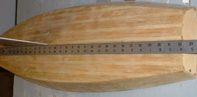
The following picture shows the way that John aligned the keel on his second boat.
Since the keel is plate and 1/8" thick I laid a straight edge on it and
aligned it with the pc at the center of the transom. I did this on both
sides to make sure it is centered as well.
To capture the top of the keel box he added 2 1/8" X 3/8" spruce blocks
to the top of the keel trunk and glued them to the king plank. The photo also shows the glass tape He used to reinforce the
radio tray.
===
here is an alternative keel trunk (from Uncle Dave)
I poked my camera down into the Sirius 45 and snapped a couple of pictures showing how the keel is attached to allow it to be removed and another installed.
The keel is a aluminum fin with my flat bottomed bulb. The keel trunk is assembled over the keel fin before mounting the trunk in the hull. The trunk is pretty simple. Two pieces of 1/8 ply on either side of the fin. Cut flush across the top of the fin. Height is determined by the amount of the fin to extend into the hull. Length is determined by the shadows or braces to support the fin. A filler pieced goes between the sides so that fin can be slid own and out of the trunk.
Before gluing the trunk up it is very important to coat the insides of the trunk to make the sides of the trunk as water resistant as you can. The the fun part is placing two mounting bolts through the sides of the trunk and thought the keel fin. I think the two bolts in the picture were 1/2 long 3/8 inch dia.
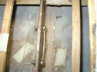
I placed a heavy wire through the both the bolt heads so I could turn the nuts on the other side.

With the nuts removed the two bolts simply push to one side and the keel fin mounted or removed as the case may be. In my models the height of the fin inside the model is low enough for a swing arm sail control to fit properly. I use Probar (now Dumas) SCUs.
Before building the deck I simply dropped the trunk (with keel fin) through the slot in the bottom of the hull so the trunk rests on the keelson. The hull being fiberglass the trunk if filleted with the bottom using some auto body resin-paste. I think I also used the resin paste to mount the keel trunk in my wooden models (memory escapes me its been years). The ends of the trunk are braced to the chine to with stand leverage forces from the heavy keel bulb and sailing stresses.
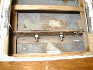
When the two bolts are tightened they not only hold the keel in place they also pull the sides of the of the trunk tightly together. With the tight fit one should expect the keel fin may stick in the trunk if some sort of lubricant (silicone) isnt used.
Making Keel Cooling For A Friend
Diposting oleh ghone | 0 komentar | 15.37Label: a, boat making, cooling, for, friend, keel, making
The beauty of these boats is they can be bought for very reasonable price, they come well equipped with quality fittings to stand the riggers of hire and the hulls are well built.
So the internal skin tank was set up for a 35hp engine, a fact the professional boat company installing the new 52hp engine somehow overlooked? Hmm?! IMO the first thing to work out when fitting an engine is how to cool it. If you cant cool it you cant run it. Well you can but so long as you dont call up all the horses or want to destroy it.
The problem only manifested itself when Sue needed to punch against the flow on the Thames, which of course needed more horses than poodling on a canal which she had been doing since the new install.
There were 2 options to solve this, another internal skin tank linked to the original which would require the engine bay to be cleared of things like the errr! engine! The other option an external skin tank, or keel cooling which is really what a skin tank is requiring just 2 holes made and welded in the hull. No engine removal and just a few hours work in a dry dock.
Theres a well regarded formula for working out the cooling area / engine hp. Its HP divided by 4, so a 52hp engine needs 13sq/ft of surface area. The most compact way of doing this is with tube, in this case 80 x 40 box section which gives 1sq/ft of surface area every 16" of length. To further compact this a serpentine patten is the norm.
This is it.
So this is what I came up with and made for Sue & Vic. See the links below as she takes up the story on her blog. Read backwards from here:- Sadly I wasnt able to fit it for her, but the local floating dry dock did a great job.
If you like boating blogs, you will love Sues. Hers is constantly ranked in the top 10 UK boating blogs, its has a great balance of travelogue, opinion, and lifestyle showing the good and not shy of speaking about the not so good. Always punctuated with great photos and on the sidebars masses of excellent links, tutorials and resources as well as a massive list of fellow boater blogs.
Didi 950 Keel Build by Howdy Bailey
Diposting oleh ghone | 0 komentar | 23.45Label: 950, bailey, Boat Plans, Build, by, didi, howdy, keel
Howdy and his staff are doing a masterful job of building this keel, which is assembled over a rigid skeleton of schedule pipes between end plates. The side plates are wrapped over the skeleton and plug welded.
One of Howdys staff welding the keel structure. |
Completed keel skeleton with pre-formed side plates awaiting fitting. |
Same stage, looking at the top plate. |
The keel bolts bear on the keel box inside the hull, sandwiching the hull skin between the the two. Howdy Bailey Yacht Services fabricated the box as well, then shipped it to the builder. He has test-fitted the Beta 15hp motor on the beds ahead of installing the box into the boat. The following photos show the box with engine standing on the integral engine beds.
Didi 950 keel support box front view. |
Beta 15 being test-fitted on the engine beds. |
Aft view. The holes are for shaft, exhaust and ventilation. |
To see more of our designs, visit our website at http://dixdesign.com/.
Glass Work Keel Bolts and Sheer
Diposting oleh ghone | 0 komentar | 19.39Label: and, Boat Plans, bolts, glass, keel, sheer, work
The top of the access stairs became a staging area for all things glass and epoxy.
During drying periods while glassing the integral tanks, Richard worked on securing the existing bulkheads/ frames to the hull. They were currently only being held by the epoxy applied during the strip planking.
In the above picture you can see the fillet in the far bulkhead joint. It is beige in color, due to the wood flour and fumed silica added to the epoxy to thicken and create structural filler. The fillet gives the joint a radius and strength. The glass fabric can not make sharp corners.
The strips of biaxial fiberglass were cut with Janes fabric rotary cutter. Cutting with scissors causes lots of fraying and frustration.
On close inspection you can see the fillet with the fabric wetted over it.
The frames were only filleted.
This shows the glassing and filleting and epoxy work while it is drying in the head area.
The cedar is pretty wetted out with a couple coats of epoxy and fillets at the frames.
View of the stem, glassed, wetted, and filleted.
Structural taping was used at places that will be covered by veneers, paint or trim.
The engine supports were reshaped to fit the chosen Beta Marine, and glassed into space. The glass on the hull is sanded smooth. The blue tape is covering and protecting the bronze rod/bolts that are drilled through the rear deadwood.
A bit of head scratching went into design and construction of the quarter berth.
Lots of fitting and scribing....
In and out the bunk goes....
This shows the final quarter berth with access holes in place.
Epoxy work in the engine compartment is completed. This will be partially under the cockpit. Side walls will frame out the remainder of the compartment.
Don Goodspeed came over to assist with drilling the keel bolt holes. They will hold the lead keel in place and it is important to get them as straight as possible.
The extra long bit is very intimidating.
A jig was created at each keel bolt site to help keep the shaft plumb during the drill.
Fingers hold the bit evenly spaced from the jig.
Not much error fore or aft would mean coming out the side of the floor frame.
The bit had to removed and cleaned several times for each hole.
There were a total of twelve holes drilled through the hull of the boat. Every one was a success!
We started playing around with cabinetry placement. This is looking forward into the head compartment. The cardboard cutout will be a bench covering the toilet in the forward storage/workshop/head area.
The starboard settee needs to be adjusted to cover the frame in the middle....
Placement and dimensions being critiqued.....poor Richard. The first-mate is particular!
To shape the sheer from the designed offsets, the sheer needed to be marked at the appropriate height above the DWL (designed waterline) at each station. The mark showing DWL remained visible under the epoxy on the main bulkhead. A ruler was clamped in place and a water level was used to find the correct placement of the sheer on the outside of the hull. The clear tubing (on left) was run out through a keel bolt hole and filled with water.
A thin batten painted flat black was clamped in place along the pencil marks.