Tampilkan postingan dengan label deck. Tampilkan semua postingan

Stacking the Deck

| 0 komentar |
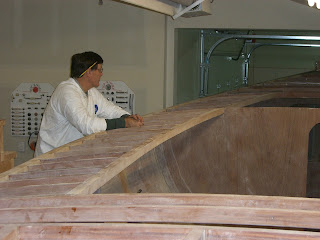
The first step in the deck planking process was laying out the lines on the subdeck plywood so I could figure out what wood I needed to do the job. I drew in a 2" grid pattern on the sub-deck to ensure that the center planking would be symetrical. Using a batten, I drew in the perimeter cover board lines to follow the carlings aft of the dash and stay a "constant distance off the shear line" forward of the dash. I made the first line drawn on the forward deck (that I liked) the "master" and copied it to the other side. There is a slight difference in distance to the shear line from one side to the other, but not enough to worry about.


Then a trip to Armstong millworks to buy some African Mohoghany for the deck planking and then learn how to re-saw. The guys at Armstrong suggested that starting with 4/4 stock planed to as thick as possible (about .90") would be the best approach.


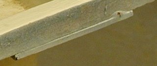
I started with laying out the boards along one side of the boat to determine joint locations to get a 12 long 10" wide board to cover the width and length. Due to the limitations of my shop, the board was cut into the pieces and angles necessary to go around the boat on one side, then each piece re-sawn to create the piece for the opposite side. With a riser kit previously installed on my bandsaw, a new 1/2" wide skip tooth blade, new Olsen "cool blocks" and a 6" tall fence, I started bandsawing the wood for the outer perimeter planking. The piece at the back of the boat was 9 3/4" wide and the re-saw went very, very, slowly, but it worked. Then a few trips through the thickness planer (new blades installed) yielded planks about .34" thick. Using countersunk screws, the first piece was located, beginning at the aft end of the boat and working forward, a joint line established, chop cut on the mitre saw, reinstalled and the next piece cut to fit up against the previous piece.
After the joints were established, the inside line location was transferred from the sub-deck to the underside of the cover boards. In the cockpit and motor opening area, tracing on the underside was straightforward. In other areas the grid pattern was used to re-create the line by tracing the inside edge of the boards onto the grid pattern and measuring to the line intersection at each grid line. Tedious, but it worked. Line was cut on the bandsaw about 1/32" proud and then sanded to the line with a small 1" stationary belt sander. Outer lines were traced, cut, and sanded in a similar manner.

The kingplank down the middle of the boat took a bit of trial and error to find a width that looked "right". I started at 6 1/2" wide, about an inch wider than the perimeter boards in the fore deck area and it seemed too dominant. At 5 1/2" it still seemed too wide, so eventually my aesthetic director concurred with a 4" wide being the "right" width.

The grid pattern helped with cyphering out the width of the longitudinal planks. Eventually settling on 1 7/8" width, and a 3/16" gap. In order to fully utilize the boards I had purchased and not have to go buy more wood, I needed to squeeze four planks from a board width of just under 7 3/4" inch. (Maybe the king plank should have been a bit wider!) This created an opportunity to buy a new tool for the shop - a micro-kerf table saw blade which only cuts a 1/16" wide kerf. After creating a new table saw zero-clearance insert with a splitter, I was all set to cut the planks. The new blade cut like butter and I got all the pieces needed to cover the deck.


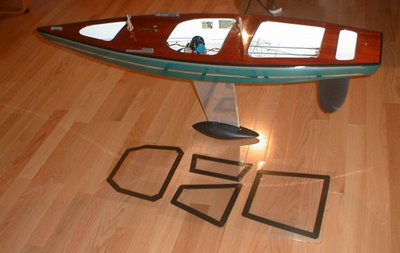
The plan at the moment is to stain the perimeter and king planks a darker color to provide greater contrast. Then finish all the planks to seal all the grain and complete the deck using a white pigmented epoxy to fill the gaps.


Read More..

Shall I Cut the Deck

| 0 komentar |
My plan is to get the boat out of the basement before putting on the deck plywood so it will be somewhat easier to handle and slightly lighter. But, there isnt any reason not to go ahead with doing the rough cutting and fitting. After a bit of sketching of how to cut the pieces, it seemed the only way to get the front deck pieces out of one sheet of plywood was to use the factory edge down the centerline of the boat starting about 18" in from the end. The opposite side piece would use the other side of the sheet but the sheet would be flipped over to fit the mirror image piece. I plan on having a natural wood finish on the deck using just the plywood but with a paint graphic band down the center to hind the seam. Luckily, the plywood has veneer that looks very similar in grain and color on both sides of the sheet. The first sheet of deck plywood is not supposed to stop at the dash or any frame, but continue as far as possible along the carling and sheer as not to create a weak spot. After positioning the full sheet down the centerline of the boat and clamping it in place, a line was traced on the underneath side to show where to cut it. A 1/4" thick scrap piece was used to offset the pencil mark to allow at least a 1/4" overhang at all edges. 
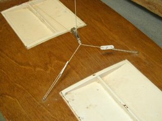
Then the sheet was taken off the boat and set up in my shop for cutting with a jig saw. I quit for the day at that point to sleep on it before cutting.


Some blue tape was put beside the cut line which minimized any tear out of the veneer and helped visualize the line to be cut. The firse piece went well as did the second. Putting them both on the boat confirmed that the color and grain look very similar between the two halves.


The next task was the back halves. The first one was marked and was left overnight just in case there was something I was overlooking. Nope, cut it and it fit. Tried it on the other side and it fit there too. So I used it as a pattern for the other side. I left overlaps between the front and back pieces to give me some adjustment when finally glued and attached.
Read More..

Sailing Model AMYA Star45 Class Construction Deck s Hatches

| 0 komentar |

from John Fisher:
Attaching deck to hull

John Fisher photographer


Hull with deck mounted:

John Fisher photographer


--------------------

HATCHES:

From Phil Geren:
The simplest hatch cover solution I have found for Star 45 is to cut a piece out of Presentation Cover vinyl, which cut-out is shaped like the hatch opening but 1/4 or 3/8 of an inch larger on all sides. Then, apply electricians tape (1/2 or 3/4" wide) all around the perifery, so that half the tape is on the vinyl and half is hanging over the edge.

Presentation Cover vinyl which I get at Office Depot is about 15 cents a sheet; it is about 0.008" thick; it is slightly over 8.5X11" in size; a full sheet weighs about 16 grams; it is stiff, but flexible; it is crystal clear, but if you want it opaque, just wet sand it with #400 grit wet or dry sandpaper.

Position the hatch cover over the hatch so that the tape extends evenly past the hatch opening an equal distance all around, and then just press on the tape to stick it to the deck. Its waterproof, durable.

You can make spares and stick them to another piece of vinyl and carry that with you to the races. That keeps spares nice and flat and keeps the tapes sticky side clean for future use. A set of these hatch covers usually lasts me all season. At lunch, I take one cover off to allow the boat to dry out, sticking the cover to a dry vinyl sheet to keep the tapes sticky side clean.

Photo is Star 45 #778, freshly rebuilt for the Nationals this year, and a set of covers on the floor next to her.


Phil Geren photographer


--
from Uncle Dave:
I pulled one of my old Star45s from the attic and have it here in my workshop. It has a fiberglass Sirius 45 hull, a aircraft ply deck and aluminum keel fin. Unfortunately it is not one of my finest examples of workmanship or painting. However Ill suffer the embarrassment and use if to show some one style of hatch construction.

Carrying around a model around out of the water is no big deal. Taking a model out of the water can be something else. You first need to hang onto the model. Then find a place to take hold to lift the model. This is one of the reasons I have used easily removable hatches. You can grab the model through the hatch, fingers under the deck and pick it up. Of course a thin ply deck the model deck and hatch construction needs to be strong enough to withstand pulling on the deck and lifting a twelve pound plus model. Therefore I braced my decks around hatch areas.

First I built a flanged frame for the hatch to sit in that also extended under the deck and attached to the deck bracing.
dlm_hatch_a.jpg

Then I built a hatch cover based on the size of the hatch. Initially the hatch cover was made to fit very loosely in the hatch. I then took some silicone (tub seal or similar) squeezed a bead around the shelf/lip of the hatch. The covering the hatch opening with food wrap poly sheeting Id push the hatch cover in place down into the silicone. This made a nice water tight gasket around the edge of the hatch. After waiting a day Id remove the plastic, trim and silicone that showed topside. With the silicone dry, pop the hatch cover in place and check the fit.

dlm_hatch_b.jpg

I placed a strip of magnetic tape on either end of the cover and on each end of the hatch frame.

dlm_hatch_c.jpg

When the hatch cover and hatch mag tapes touched they pulled together. This magnetic tape is neat stuff you can pop the cover in place and it will stay put.

Typically I made my hatches about 4"X5" giving me plenty of deck to the sheer.
fixed_travelersml.jpg

I heavy weather if the model might go over on beams end Id cover the seams with tape just to be extra watertight. A 4X5 hatch gives room to get inside, adjust winch, radio etc, and to remove any water that got into the bilge while sailing.

Read More..

Rear Deck Boards

| 0 komentar |
A while back I made some templates for the back decks from the temporary working decks Ive had since 6th July 2010


I took these to a local firm that make ply lining for vans.  The have a couple of CNC router decks.  From these templates they digitised then cut the Wisadeck panels.  This board is difficult to cut as it splinters very easily if cut with a saw.   


The router cuts a nice clean square edge and the curve is nice and continious.  The edges were then beautiflly painted and sealed by SWMBO.
Read More..

Deck Staining

| 0 komentar |
When we put in a patio I thought I would never have to stain a deck again.... After hand sanding all the deck surfaces with 220 grit, some vacumming, wipe down and room clean-up it was time to mask and stain. A bit of blue tape, plastic and masking paper and I was ready to have at it.
After staining everything, there were some blothy spots around one of the perimeter planking joints and a couple of sanding scratches on that same side. After letting it sit overnight, I still was not satisfied with those areas. So I hand sanded again with 220 grit one whole side, cleaned it up and restained. Its good enough now to move on. Looks pretty cool even if I say so myself.
Read More..

Starting the third year by mounting the deck frames

| 0 komentar |
January 2011 was the beginning of the third year of the build. With meticulous records Richard has totalled 2693 hours. He originally calculated 5 to 6 thousand hours to completion....about the half way point?
By subtracting out the 13 weeks lost to building due to injuries and other obligations, but not removing other short times off to see the kids, travel to boat festivals, etc he has averaged 30 hours per week on the boat. Sometimes he works as much as 60 hours per week, especially at times like preparing for the boat rolling.


View of the saloon bulkhead that will be raised to cabin height.


Glassed in subfloor over the integral water tanks.


Glassed and sanded main bilge area with the engine compartment visible in front of picture.


Support framing for the deck and the back lazarette was created at the transom. The sheer was notched and frame pieces mounted to the transom to hold the quarter knees.


After fitting, the quarter-knees, frames and brackets were sanded, finished with epoxy and prepped for mounting.


The brackets between the quarter-knees frame out the lazarette.


The bracket is cut up to allow access into the sides.


Back frames are added to support the hatch.


All frames are epoxied in place and clamped.


Clamps at every angle.


Richard has been being diligent about wearing his "sperm suit" and respirator while doing epoxy work. He started to develop a burn type rash on the inside of his lower arms while using
epoxy in short sleeves. Sanding partially cured epoxy also seemed to increase the irritation. So back to full coverage.


The cockpit was constructed from 3/4" marine plywood. Since creating a smooth nice fillet on the inside corner was a challenge, Richard trimmed and used a piece of cove moulding. The floor of the cockpit will be glassed and epoxied seperately. The rabbet around the bottom of the well will increase the epoxy surface and the floor will be be screwed into place with bronze screws.


A compact cockpit, but since she has a tiller, there will be no binnacle to hog floor space.


A nice view of the frames in place. The center is the cockpit, the left and back are lazarettes.


I couldnt resist another pic of the sweet transom.....


I tried another view, but it is pretty distorted.


More finish epoxy work, fillets, and sanding of the entire inside.


The entire inside is sanded and cleaned.


This is looking into the port side lazarette.


Now....to start fairing the deck frames......lots of arm breaking work to get the tops of the frames smooth in relation to each other.
Read More..

S45 Construction Deck

| 0 komentar |
4/19/2007 John Fisher just finished the deck rigging last night on his latest boat. The boat is set up pretty simple. Open loop with elastic. Winch is below deck, but the same rigging setup can be used with an on deck winch, just substitute a turning block for the through deck block.

The sheets go forward to a block on a bridle for the main sheet. The jib sheet and elastic go through a double block attached to the chain plate to keep things from rubbing on the mast, then through an adjustable double block forward. The jib sheet then goes back to a deck mounted block. The elastic is then hooked to a loop on deck. John put a hook in the elastic so he can release tension when in storage.

Chain plates and mast step are laid out per Scott Rowlands tuning guide.


In tweaker photo bellow you can see the tweaker servo and winch mount.

Read More..

The Deck the Deadwood and the Frig Box

| 0 komentar |
Well.... Summer of 2011 has definitely ended in the Flathead, but it wasnt all work, as we enjoy a little sailing on Flathead Lake, and a toddy with our sailing friend and mentor, Don.


The finish work to the interior is coming along nicely with many coats of paint and varnish. Everything seems to wait for something next to it to be completed.
I finally caught a day when it was fairly cleaned up....and suitable for some interior shots...


This is looking aft. The companionway will be over the engine compartment. The right side of this counter is part of the galley. The beadboard area is planned for the electrical panel.


This is looking across the saloon toward the fore storage/head area. That bulkhead will be covered with beadboard after being extended up to the cabin top, after the cabin sides are built.


We painted the settees, under the cushions, for easy touchup and durability.


Finally, everything he wanted to do prior to deck application was done.....Early August brought the deck sheeting.


Richard had reservations about the stability and strength of 2 layers of 1/4" meranti plywood for the deck. He had concerns about how to place the joints, and their ultimate strength.


He made sure the first set of joints landed on a deck beam.


Cardboard templates were used for fitting pieces around cockpit and transom areas.


After the fitting, each piece was scarphed so that the joint centers on a beam.


This was done by angling the piece vertical on the table saw. (the advantages of tall shop ceilings) The 12:1 scarph joint theoretically a whole lot more flat grain vs end grain is being glued up.


The feel and size of the exterior and interior is starting to become apparent.


We are glad we went with a wider cabin. Possibly less traditional, but she will be our home.


View from cockpit forward. The underside of the decking had the areas where the deckbeams fell taped off and the remainder sanded, primed, and a first coat of paint applied. This would make the underside easier to paint after application. Painting and sanding overhead is never a pleasant job...but epoxy needs raw wood for the best adherence.


The first layer of deck is ready to be epoxied to the deckbeams.


Messy, messy.... big sheets, fumed silica thickened epoxy, and lots of scarphs have to all fit correctly and not slop onto the finish work inside.


Lots of good hold at the scarphs.


The second layer was laid out with joints staggered. These were not scarphed as they had the first layer as backing behind all the joints.


Cut and fit....

The thicken epoxy is mixed......foam rollers used for application.


5:1 mix of the RAKA 900 epoxy was used to provide the best tolerance to potential deck heat. Richard does not want the epoxy to "resoften" in the heat of the tropical sun.


Unfortunately the mix has a higher level of allergy risk. Extra care needs to be taken to avoid exposure. A post exposure rinse of arms and hands with vinegar then water helped to ward off any allergic reaction.


Ring shank nails into the deck frames and 3/8 plastic staples in the field hold the layers tight together for the drying/bonding.


A cured and trimmed deck is a beautiful thing.


Plenty of fasteners.....the plastic staples are sanded off during the fairing process.


The deck imperfections are filled and sanded.....of course, the long board is used for the final fairing.


The deck edge is trimmed flush to the hull and a 3/8 radius was routed at the top to allow for the "cloth" to roll from deck to hull. The rub rail will ultimately cover this joint. I think this joint is a key to a dry boat.


Next step is the refrigerator box. We decided the nav station lower cab was the best suited for our needs. So much insulation is needed that the size quickly diminishes. The box is square with an angle for the hull.


The insulation was purchased in 3/4" thick sheets, with reflective backings. It will not absorb moisture, and has an R value of 6 per inch....it is a total of 4" thick.


It was layered into a plywood box, with the directions of the corners alternating to prevent potential air spaces and heat loss.


The construction design decided upon came from Don Caseys This Old Boat.


The tops of the insulation have flat areas and angles to provide gasket areas and insulation transition to the fitted lid.


The lid is cut from foam and angled to fit, then covered with glass.


The insulation is glassed, then filled in numerous small steps to make a smooth finish. The crew appreciates a smooth finish for future cleaning.


The lid is filled and faired.


Box is getting pretty small, but we opted for more insulation and less space. The "freezer" will be the shallow end, and a divider will be placed after the evaporator plate arrives.


Oops....a chunk of insulation came out of the top of the lid while attempting to do the Don Casey method of lid fitting....squeezing the epoxy out between the lid and sides......yikes....oh well, only a minor repair and fill.


And now, its time to address the prop apperture. Mark did a little rework on the plans of the deadwood to help reduce potential for turbulence. He also added a trim tab to our transom hung rudder, to assist in wind steering.


The area is filled in with laminated muranti.


This area will be shaped into a double hourglass to accommodate the smooth flow of water over the prop. The tricky part for us was visualizing how the area above this flow.


It needed to be faired with the hull, and brought back to the plane of the transom and meet the transom hung rudder.


After the glass was ground away for adherence, the first layer was epoxied.


Then bronze screws were placed to reinforce.


As the area was filled in, the shape of the flow became more evident.


Some nice hefty fillets did the trick....


A little clean up with the sander....


And a new toy, a head for the grinder, will do the actual shaping.


This carbide head is VERY aggressive and will hog off material fast....Im thinking protective gear should be worn while using it....


Next came the "glassing" of the deck.


The highly abbrasion resistent "glass" was laid out over the deck.


The interior was draped to protect it from drips.


All the little edges were smoothed and fitted.....and yes, the head room remains tight....


The fabric was rolled over the edge onto the hull and taped.


It seemed like having it smooth and ready was the way to go....


I think Richard was hoping for minimal "creep" when applying the epoxy....


Unfortunately it tried to walk all over. But setting up and having it fit ahead of time made it go on smoothly and with smooth seams.

Her lines still please me immensely......


After trimming, the deck edge looks great.


Hopefully a strong seam, with no leak potential.....the deck feels very stout and solid.


Next will come deciding how to build the cabin top with its compound slanting curved sides and arched top.
Read More..