Tampilkan postingan dengan label Building. Tampilkan semua postingan

McGuiver goes boat building!!!!

| 0 komentar |
Sunday 16th december 07

Today, I went mad..... In my wisdom I decided FR 14 was going in whether it liked it or now.
No crane, nobody else but the boys. so the gentle art of "McGuiver" came into play.


Step 1. Load heavy Frame onto truck tail lift.


Angle it upwards and drag it onto the scaffold tower


Roll tower to bow and shove it onto the tops of the hull.

Now, this piece has to be fitted by dropping it straight down onto the centre piece to support it.


Build the above contraption form whatever is to hand. and attach a 250kg wire winch to make a crane (we use these for lifting lighting gear. )


Add a 5yr old boy to press the buttons.. explaining the dangers and how much is "a little bit" ....


Voilla... Dara does a great job.


Fitted like a glove.
Read More..

Building the templates for the frames

| 0 komentar |


I decided to make templates from the plans for most of the parts in the frames. Using the carbon paper, lines were traced onto material to make the templates. The actual frame pieces were then rough cut, stacked together with double backed tape, the templates double-back taped to the pieces and a trimming router bit with guide bearing used to cut multiple pieces at the same time. In the corners where 1/4" plywood gussets were used, 4 indenticle parts were made at the same time.


With African Mohogany purchased from Armstrong Millworks in Highland Michigan and Okoume plywood purchased at Public Lumber in Detroit, the frame build got started. The same layout board was used as an assembly jig. Blocks were screwed down to locate frame members so that epoxy gluing, screwing and or nailing could be done while maintaining alignments.
Read More..

Building Stocks for Wooden Boats

| 0 komentar |
There are a few ways to construct building stocks for building a wooden boat but most are variations on the basic method that I will show here. These photos have been sent to me by Fred Grimminck, who has previously built our Didi Mini and is now building the bigger sister, the Didi 950. This is a boat that is designed to fit into the Classe 950 Rule. It is a radius chine plywood boat with hard chine in the topsides.

Freds building stocks, or beds, are on short posts that are fastened to the concrete slab in his workshop. If he were building off earth then the posts would be extended down into the ground about 300-400mm and set in concrete to make them stable. Other than that, the rest of the configuration would be the same.

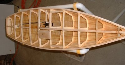
Click on photos to enlarge, to see detail.
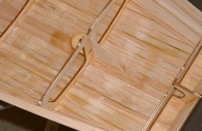
Didi 950 building stocks looking aft.
Didi 950 building stocks looking forward.
Rails and transverse braces are bolted to the posts. It is good to set the rails accurately so that they can be used as an accurate reference at any stage during construction. That means setting them so that the tops of rails and transverse braces are level, with the centrepoints of the transverse braces on centreline and the rails identically positioned each side of centreline. If any bulkheads will be attached to transverse braces then those transverses need to be set up at 90 degrees to the centreline, which will happen automatically if the two sides of the beds are identical. The centreline string on the beds can be seen in the photos above, providing a good reference for checking accuracy.
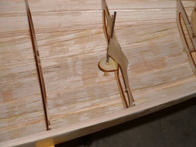
Transom doubler being set up on beds.
The photo above is of the transom doubler being set up on legs that are bolted to the aft transverse brace. If the transom will not have doublers on the inside then the transom itself would be in this position. This attachment is done in the same way as a bulkhead except that the bulkhead legs are generally bolted to the rails instead of a transverse brace. If you zoom in on the photo you can see the small piece of steel angle that Fred has used to fasten the post at bottom right to the concrete slab. The angle is bolted to the leg and to the slab. This must be done for all of the posts.

A secure and accurate set of building stocks is the foundation for an accurate build. Another essential to get this right is for the waterline and centreline to be accurately drawn onto every bulkhead. These lines will be used in setting up the bulkheads themselves and also many times during construction to set up joinery, engine alignment etc.
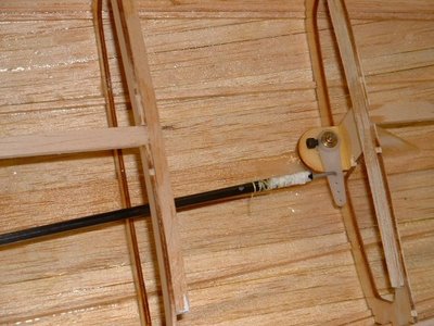
Didi 950 bulkheads being set up on beds.
 Fred is working forward from the transom in setting up the bulkheads but you can work from either end. I normally set up the forward bulkhead first, then work aft. This is because the forward bulkhead may extend below the top of the stocks and need to be either clear of the front transverse brace or attached directly to that transverse.

In Freds photo above, the bulkhead closest to the camera is at the front of the cockpit, so forms the aft end of the cabin and serves as a good example. Each bulkhead must be set up accurately in all directions for the hull to be built to the shape intended by the designer. It must be at the correct location fore/aft, laterally and vertically. It must also be square to the centreline and it must be vertical both fore/aft and laterally.

Correct position fore/aft is done by measurement from the first bulkhead that is set up. Check it also against the distance to the previous bulkhead because this will highlight previous errors that may have been missed.

Correct position laterally is done by means of a plumb bob hung from a line above the stocks that is exactly over the centreline of the stocks. In a building this line can be attached to the ends of the building. If outside it will need posts to be set up beyond the ends of the hull and the line strung between them. The plumb bob is visible in the photos above.

With the plumb bob hanging from this line you have three checks that can be made on each bulkhead. They are lateral position of the bulkhead, vertical alignment of the bulkhead face against the plumb bob string and vertical alignment of the centreline drawn on the face of the bulkhead. This last one is a basic check that one end of the bulkhead is not lower than the other end but is a check only, not the place to set it up accurately.

Correct position vertically can be done with a waterlevel, which is a whole subject of its own and best dealt with in a separate post. An alternative and quicker method is to use a land surveyors theodolite or a laser level that can be set up beyond one end and to one side of the beds, with a clear view of the whole length of the beds. Use this to horizontally align the waterline marked on each bulkhead so that both ends are at the same level and all bulkheads are aligned to that same level.

When each bulkhead has been correctly set up, bolt it to the support legs and brace the legs to prevent movement. Once all bulkheads are aligned and secured, you will be ready to start adding longitudinal structure.

A few things about this process should be noted.
  1. Wood is a living material, it changes dimensions with variations in humidity and temperature. If you set up a bulkhead on a dry day and a week later you set up the next bulkhead on a humid day, you will find that the dimensions may have changed by a millimetre or two. Work as accurately as you can but dont sweat over these minor changes. If you do, you will chase yourself around correcting and recorrecting whenever the weather changes. Just accept the changes and move on. Constructing the stocks from steel will stabilise them from changes due to humidity but not temperature. If you are like me, you like to work with wood and really dont like working with steel, so you will stick with wood for the stocks as well.
  2. Dont attach the legs to the stocks or to the bulkheads with wood screws, through-bolt them or use lag screws. Each bulkhead will not weigh a lot when you set it up but by the time that you have added backbone, stringers, sheer clamps, hull skin and possibly even built much of the interior, your wood screws may be bending or even sheering off under the load.
  3. A solid foundation to build your hull is the principle to aim for. Use diagonal bracing to keep everything at correct relative positions and angles.
  4. You need to be able to get through between the structures of the building stocks and the hull as it takes shape. You need access at many positions along the hull, not just aft under the transom. That needs the longitudinal rails of the stocks to either be hard against the slab or lifted enough to slide under. I recommend lifting them enough to slide under, which is easy by grabbing the rail with both hands and swinging your body through. If the rails are on the ground you need to hang onto the sheer clamp or some other structure to swing through and you will likely suffer numerous bruises to your back from impact with the rail during the course of the hull construction.
To see more about our designs and buildign methods, please visit http://dixdesign.com/.
Read More..

Im often asked why Im building a boat

| 0 komentar |
Well this was my plan, but like all good ideas its been nabbed.


Dont tell Deb though.
Read More..

Post apocalyptic Boat Building

| 0 komentar |
Why build skin boats?  Ive been asking myself that ever since I started building skin boats.  Ive come up with a bunch of practical reasons such as low price but thats not really why I built them. First and foremost I liked the looks of skin boats.  But right up there with good looks was also a yearning for self-reliance.  I wanted to be able to build a boat that at least in principle I could build entirely from scavenged materials with simple tools that if need be I could make myself.
For the sake of convenience, I use electrical tools to cut the wood and synthetic fiber cloth as a skin and petroleum based paint to seal the skin so I dont really build an entirely off the grid boat.  But I like to imagine that I could build a boat strictly from found materials in the manner that people of the Arctic once did.  In a way, the Arctic before the arrival of the Europeans was very much like what a post-apocalyptic (PA) world would be like.  No stores, no factories, no electricity.  Everything you wanted you had to scrounge or barter for.
But a PA world would not look exactly like the pre-industrial Arctic.  A PA world would have a lot of stuff from the industrial world still laying around like scrap metal, wire, plywood, tar and even ready to use hand-tools.  A PA world would not be a stone age world necessarily.  It would be a world that had very little new stuff in it. If you wanted new stuff, like a new kayak for instance, you or one of your friends would have to make it themselves.
Could I build a boat entirely from scrounged materials in a PA world?  Probably.  More than likely, if I wanted a boat with some cargo capacity, I would probably scavenge plywood, and make it out of that.  I dont know what would be available in the way of sealers to keep the boat from leaking, but I could probably find something.
If I wanted to build a skin on frame kayak, that would be fairly easy.  Plenty of construction lumber installed in buildings. I am assuming that I could get some hand saws.  The hardest thing to find would be a suitable skin.  I imagine myself scrounging tarps or awnings and sewing those together, again, assuming I could get a hold of some needles or maybe even make them from bone.  If the tarps were plastic, they wouldnt need a sealer.  If the tarps were not plastic, I would have to figure out a way to make them waterproof.
Hunting sea mammals for skins would be more or less out of the question.  That would require more skill than I have.  Even if I could manage to kill a sea lion hauled out on a beach by stealth, I would need four skins to cover a kayak.  Getting four skins would be way too ambitious.
But how exactly did people of the Arctic build their kayaks in a pre-industrial world?  We have some ideas but Europeans have been going to the Arctic since the 17th century and most of the kayaks now in museums were built with at least some access to steel tools and also possible to milled lumber.
The pictures below show what kayak building looked like in the transitionary period when people in the Arctic still built kayaks, but had industrially sourced tools and materials available to them. The kayak type being built here is Eastern Arctic, that is Canadian Arctic.  These kayaks were long flat and stable and if you killed a seal, you transported the carcass on the wide back deck of the kayak.

Heres a guy in his open air workshop, no special jigs or benches or other sort of stuff you would expect to find in a boat shop. But he does seem to have a handsaw that he is using to trim something in the cockpit area of his kayak.
This guy is sitting in his workshop.  Hes using some rocks to level out the deck of his kayak.  Hes got the rib blanks stuck into their mortises, all ready for bending and trimming. Or maybe he is going to do three-part ribs with hard corners.  Also not the canvas tent in the background. 
Here two people are working at putting  a skin on the finished kayak frame.  The skin is canvas, not seal hide so one or two people can do the job.  Putting on seal hide usually was a task for many women since the hides had to be kept wet and pieced together which required way more sewing than was practical for one woman to do by herself although it was probably done solo sometimes by necessity. Also not the wood plank in the foreground, evidence of milled lumber brought into this location, probably by ship. Also note the long wide and flat back deck suitable for transporting  the spoils of the hunt.

So what can we say about boat building in an imaginary PA world? Probably possible as long as nobody has any set ideas about what is allowed in the ways of tools and materials.
Read More..

Steps toward building a sailing model

| 0 komentar |

Building Displaying Sailing
Model Boats and Ships

So you want to build a sailing model
Find plans for a sailing model, buy or find on-line.

Join a model boat forum for advice.

Buy or borrow books on boat building.

Decide on type of planking and wood to be used to build the model.

Set aside a work space for building.

Review the bill of materials need to build the model and buy the materials.

Order deck and mast fittings.

Order mast (if you are buying the mast) and order sails (or sail material).

Choose the radio system, buy a sail control unit, Order keel bulb or get advice and discuss issues of building your own.

While the hull is under construction build:

Keel fin and ballast bulb

Rudder assembly

Make or assemble spars ( mast and booms)

Build cradle to hold boat under construction and when finished.

Test Radio System and sail control unit

After hull is planked:

Install keel trunk or make provisions for mounting keel.

Install radio and sail control unit, Then remove while construction continues.

Construct deck and hatches

Install/mount deck fittings

Test access to radio and sail control inside the hull.

Provide a exit guide for radio antenna so it can be attached to mast or stays.

Install power switch for turning off batteries

Test mount keel

Paint hull, rudder and keel

Assemble hull, rudder and keel

Set up mast and boom.

Install radio controls.

Check running rigging.

Attach Sails

dry sail model

--

Sail
Display
Storage
Read More..

Building Phil Bolgers Harbinger

| 0 komentar |
Back in 2002, I received a request from a customer for a pretty Catboat. I cant remember the initial wish-list, but when I showed him Phil Bolgers Harbinger design, he was hooked. Harbinger is a Catboat of the New York model, rather than the better known Cape Cod model, and she has exceptionally fine and easy lines.
?
Fine lines
?
?
Easy bilges
?
Harbinger was designed with rowing as the primary source of auxilliary propulsion, and the New York model was much better suited to this than the more buxom Cape Cod hull-form. Phil had designed the boat to be built plank-on-frame carvel, but as the customer intended to leave the boat out of the water on a trailer, we had to come up with a different method of construction - carvel would open up when dry. The most obvious options were, glued strip-plank, glued lapstrake, and cold molded. I decided to go for strip-diagonal cold-molding, and wrote to Phil to get his permission. He was very happy with my construction plan, but indicated that he was frightened by the labour-intensive nature of the method.
??
The boat turned out to be very successful in construction and use, and Id love to build one for my own use. Very briefly, here are the primary stages in construction: -?????????


?
MDF Molds set-up.
?

7mm WRC strip Planking.


First of two layers of 3mm Hoop Pine diagonal planking.


Lots of staples needed in hollow sections - used a total of 18 thousand, put in individually and pulled out by hand.


Diagonal planking finished. Hull thickness 13mm (just over 1/2").


Shapely and massively strong hull.

?
Launching day.


First sail.


Phil Bolgers Harbinger
When I can get around to it, Ill put up a photo gallery showing the construction in more detail.
Read More..

Sailing Model AMYA Star45 Class building rudder

| 0 komentar |

Here are some photos showing one way to build a rudder quickly and easily. The quick overview is cut out the shape in a thin material, tape the sides together, insert the rudder shaft, fill the inside of the rudder with epoxy. This takes about 10 min or so to do. Followed by installation in your boat.

John Fisher

Lay out the rudder shape on a sheet of 1/64 ply. On other class boats John used a single layer of a 6 oz carbon fiber layup, so you could also lay up some fiberglass for use on the star. To do a glass layup, just take a sheet of 6 oz or heavier fiberglass, a sheet of lexan or plexiglass, and some resin. The first step is to spread resin on the plexiglass, then apply the fiberglass and then make sure it is all wetted out. Once cure flex the plexiglass and the layup will pop off.

Shows the two sides cut out of plywood, these could be fiberglass instead. Straight sided shapes like shown and the star plans are easier to make.

Tape the two sides together with masking tape. With curved shapes He taped them together then insert the shaft and resin. If you use straight sides on the rudder you can tape one side and then open it up like a book, apply resin, then close and tape shut. The open book method uses less resin but only works with sq or straight sided shapes.

Note the bend John put in the shaft to prevent it from turning inside the rudder.

Shows the top open to pour in resin. John uses a syringe to pour in resin once the shaft is in place. You can add micro balloons to the resin if concerned about weight.


Installing Rudder in Star 45

rudder brace

rudder tube


tiller

rudder link

John Fisher photographer

Read More..

DIY BOAT BUILDING GALLERY

| 0 komentar |
                                                                              All frames had been cut to fit  and  temporary assemble indoor.70% of the lumber I used are 2nd hand cengal wood. Frames and keel are transferred to a larger space at my yard for assemble.
                                                            Stem that cut to desired shape and  fitted to the stem knee.
                                         
                                        Installing the deck plate
                                                 The chines are up,by wrapping the part that needed for bending with some rags and soak with boiling water,this way will soften the lumber to make bending easier.

                                               Bottom battens are added to the framework.

                                                 Side battens and sheer clamps fitted in firm and aligned.
                               
  This is the outboard mounting transom which I extended out off the original plan.     
                            
They are my buddies,thats all the tool Im having.so far so good,going to add in a router and orbiter sander later on.What do you think?Awesome right?
    
  Below are free plans which I"d downloaded from the net.there are quite detailing  and useful for anyone who like to start a DIY boat project.Is a 21-ft cabin cruiser plan.What I did was expended the scale of 1:1.5.That is 150% from the original size.Extra frames are needed to add in as to the expansion made.


                  Video clips of boat building are essential sources for collecting info and techniques of how others DIY and professional boat builder had build their boat.Id ran through hundreds of videos from youtube and other sources and gathered  as much info as possible to assist my project.
                   Here are some inspiring and helpful video to share.
                          
?      11-Jan-2012
      Has been three moths since my first post,this project is out off my schedule,never thought that the works are getting harder and time consuming,it OK,that doesnt kill me,my spirit is still high.,a lot of mistake been made and redo,two chine stock has been broken,both chine are split from a single lumber and not noticing there is knot in it although is a solid knot,it broke while bending them.
                                                                                                                                                                    So far Ive added 9 frames to the hull structure with the total of 14 frames compare to the original 5 frames structure given in the plan due to the expansion Ive made.although frames spacing two feet is not favourable but Ill add more supporting structure like bulkhead and so on.To fare the entire structure to flush with the plywood plank is my next job.Meranti marine plywood BS1088 is the highest grade here in Malaysia but I cannot afford it,instead off that,Im going for another grade,they are marine plywood too,using local hard wood ,which also meet the BS 1088 standard ,saving half of the cost compare to Meranti grade.
                                                                                                             
   The outer stem was shaped by hand and  double framing transom or maybe Im just over concern about the weight that the transom is taking.                                                                                                                                                                                                                                                                                  &n
Read More..