Tampilkan postingan dengan label up. Tampilkan semua postingan

Thumbs Up For Customer Services

| 0 komentar |
First heres the roof with the tape removed and the surplus grit swept off.  The weather didnt behave so it still needs painting. Oh well next time.


The photo of the mushroom vent surrounds wasnt very good on the last blog so I took some in daylight.


So on to customer services.

Ive been having a few teething troubles now the boat is being used in the real world.  First the Central Heating boiler has been problematic for a while now.  It failed last week and gave the error code for a faulty thermistor.  I was kinda pleased that something had been signalled.  A phone call to Mikuni and as usual their first class customer service had one send out FOC for replacement.  Its my guess / hope this has been the problem all along and the unit will perform as it should for years to come.

The other issue that came to the fore was the generator & inverter charger not being happy with each other.  Sometimes the charger would charge other time it wouldnt until this week it just wouldnt even try.  Also when the electric oven was on with the generator running last week and the charger on the charger would drop in and out which is not right, the generator should make up the load but the Victron controls all mains coming in so it has to be set right.

A call to Victron in Holland to discuss it with service / support started on a trail of investigation.  First I had to plug it in to shore power to see if it would charge on shore power.  Sure enough it did.

When I bought the inverter kit I decided to get the PC interface so the parameters of the Victron could be read and reset and altered without using the fiddily dip switch option.  The software and drivers were downloaded from Victron then another call to Victron and I was talked through some alterations to the default settings and hey presto everything is talking and working together. Thaks very much to customer support at Victron.

Heres a couple of screen shots of the control.  The data displays in real time.


These 2 panels show input voltage which in this case is the generator, the amps being drawn in this case by the charger, the charge voltage, chargeing amperage, the mains frequency and the mains ripple, or how clean the supply is.

Theres a whole load of other information which to be honest I have no idea about, but I think on balance the PC interface was well worth the money as I will use it to monitor things in future.  Im so impressed I have ordered the PC interface that goes into the battery monitor which can store nearly a months worth of data on what the batteries have been going through.
Read More..

New Gas Main

| 0 komentar |
After discovering Id installed the gas main wrong by using soldered joints I had to re do it.  This involved a bit of cosmetic damage to get at the old one to remove it and replace with the new.  This will be fixed in due course.

So now all joints are made with compression fittings and all joints are available for inspection and adjustment if necessary.


Well you get the idea.  I have done the soapy water test which it passed and the Mk1 nose test and at the weekend I will be borrowing a manometer to do a drop test.  And for full belt and braces I have booked a gas safe inspection as well.

I finally got around to fitting the gas struts to lift the bed.  


And finally an Ahh! moment out of the window today.

15 goslings!
Read More..

All Fired Up

| 0 komentar |
Just a quick post today cos I wanna share.

With the help of my dad on the ignition key I pressurised the fuel tank and got the engine to fire up.  Even without the exhaust connected it sounded sweet.

Earlier in the day I connected up the cooling water intake and with the aid of a hose pipe from the mains I started up the generator and was able to run it at duty speed.  Previously I had only been able to run it in a protected mode because there was no cooling water, and then only for a few seconds  Seems that if there is not enough water flow it will run in protected mode only.

So all diesel powered systems are working.  Central heating boiler, generator and main engine.

Photos to follow.

I have now connected the new power take off cables from the battery pack. 95mm/square cables which needed end terminals put on.
Read More..

Love Him or Not Book Review

| 0 komentar |

 
Book CoverCapt. Larry Simns has probably had some effect on your life if you are in any part of the seafood industry, if you like to fish, if you are concerned with water quality, if you love to eat seafood, if you live or work near the Chesapeake Bay and its watershed, are a politician in the Maryland State House, or for a variety of other reasons. If you dont know his name, or the only thing that you do know about him is his name, then you should read this book.

In the newly released The Best of Times on The Chesapeake Bay, An Account of a Rock Hall Waterman, Capt. Larry Simns (the n is silent), and co-author Robert L. Rich, Jr. tell the story of how he grew up in the small harbor town of Rock Hall on Marylands Eastern Shore. He began his education in seafood harvesting at six years old, he went through brutal but valuable apprenticeship with seasoned and unforgiving Captains in his teens and he grew to become a respected Captain and seafood business owner in young adulthood. He recounts how he reluctantly found his voice as he began his rise within local groups of watermen to become a legendary advocate for them and the Chesapeake Bay in response to critical declines in seafood populations in the early 1970s. In his 40 years as President of the Maryland Watermens Association, he was not only recognized for his work by professionals with interests in the fisheries from Maine to Alaska and the Gulf Coast, he also worked with Senators, Governors and U.S. Presidents.

If you spend any time with a waterman,it would be difficult not to notice that theirs are very tough jobs. Many of our neighbors start their day at 3:00am. They work when its 20 degrees outside. They work when its 100 degrees outside. The brutal apprenticeship that Capt. Larry went through was important for learning to live in an environment that might be idyllic one moment and potentially deadly the next. There are some very exciting moments in the book. In fact, Capt. Larry went through more than one situation where he almost didnt survive.
 
He clearly explains how various finfish, oysters and crabs were harvested, having experience with pretty much every method used. He explains how "The Bay" changed after Hurricane Agnes. A resulting drop in seafood harvests coincided. Other factors including pollution from other sources led him to the chain of events that made him the powerful advocate he is. He discusses how he worked with others from various disciplines including biologists, environmentalists, and others to create policies that were not always popular. An amazing journey for a waterman from Rock Hall, Maryland.
 
Theres a whole lot more here and I highly recommend this book. Most of the chapters are brief, but full of information. It provides an education about the Chesapeake Bay, Eastern Shore life, the history of its watermen, issues surrounding its protection and much more. One gets the sense that, knowing he wont be around forever, he would like for this book to help pass critical information to those for whom stewardship of the Chesapeake and the life within it will pass. We should pay attention.
 
For more information go to: 
http://www.thebestoftimesonthechesapeakebay.com/

Book Details

The Best of Times on The Chesapeake Bay, An Account of a Rock Hall Waterman
Lived by Captain Lawrence William Simns
Written by Robert L. Rich, Jr.
Illustrated by Ann Crane Harlan.

ISBN: 9780764342776Soft Cover
288 Pages
42 illustrations


Read More..

Tidying Up Day

| 0 komentar |
I tidied up some wiring today.  I enclosed in flexi trunking the remote start cable for the generator, the output cable and the power cable for the bilge pump, and connected the immersion heater wiring and a few other little jobs.

 The end of the run

Once done I fired up the generator with the shore power still plugged in and the auto switch over worked both in and out seamlessly.  I still have to install the bilge pump but the wire is there now.

I finally got the remainder of the plinth for the bathroom so installed that and while in there I siliconed the toilet in as well

I put the recessed fender mounts in on the port side and have been doing some work on the rudder.

 
I also filled and calibrated the water and waste tank gauges.  Well the waste water one was manufacture calibrated as it was matched to the depth of the tank, but I filled the tank to check it.  The water did need calibrating whic was simple following the manufacturers instructions.  

The waste tank is showing just over half now as I also got to test the self pump out system, which as you can see as the level is down works.


Another little job thats been hanging around is the fitting of the handles and locks for the gas and kit lockers on the stern of the boat.

Read More..

Clean up after yourself google

| 0 komentar |
There is a widespread belief that technology creates energy.  It enables the delivery of energy but it does not produce it.  You cant use technology to create energy.  Energy exists of its own accord.  Technology helps with the delivery.  Thats all. Obviously there is a lot of technology involved in the delivery of energy, and the two, energy and technology are so closely intermeshed that it seems hard to tell which came first, an instance of the chicken or egg first question.
Broken widgets.  I think they used to have different pictures in them.  Now they all say lets fight hunger together.  They should say instead, If you break it, you should fix it.  But thats my point.  Technology needs a constant input of energy to keep working.  In this case, I think I will just get rid of the broken widgets, once I get enough spare energy to do it.  Clean up after yourself Google.  Thats what I would say if Google was my kids.
Anyway, I dont care about this argument.  The only reason I brought it up is that some of the google widgets I put on the sidebar of this blog have stopped working.  Google informed me that they would by way of an email.  And sure enough, they have stopped working.  But now, I have to expend energy to fix the technology.  so thats my point.  Technology eats up energy.
Read More..

A frame goes up and an auspicious arthropod goes down

| 0 komentar |
Frame 5 is the first to go up!
Floor 5 was situated about a quarter of an inch too far aft. One solution (and probably the proper solution) would be to replace the floor. I just shaved a quarter inch off of the timber real quick with a Skillsaw and chisel. Ramon was my hero in making it plumb with the plane when I got too frustrated to continue.

Treating bare wood with copper napthenate preservative.


And shes up! Three 3/8" bolts on each side. All wood-to-wood contact surfaces were soaked with copper and bedded in tar.


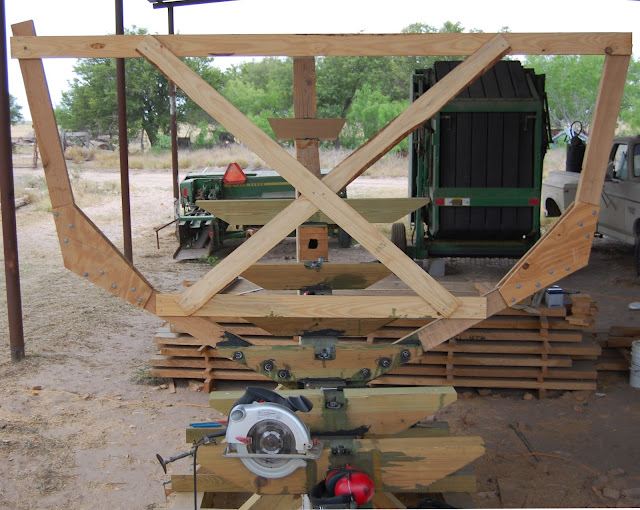
The "X" bracing and the cross beams at the sheer and just below the chine are temporary bracing.

Not the neatest job, but shes strong and deadly to fungi.

The first frame went up last night after a bit of a boat hiatus. Some coaxing with a Skillsaw and chisel got the frame to where it was supposed to hit the rabbet. Its nearly plumb, too. I apparently did a horrible job installing the floors, as three or four of them are not plumb nor flush with the station lines drawn on the keel. Ill be spending a lot of time over the next few days correcting my mistakes with a plane. This part of the boat building process has become tense as I anticipate bending a batten around the chine for the first time. I hope Luna will be beautiful.

Lucky for me, the universe sent me an auspicious sign this morning to calm my nerves.

I woke up at about 4 am this morning to a smelly, wet substance on my arm. I flung on the lights and, without my glasses, saw a blurry yellow puddle with a long, black swirly piece of business on my sheets where my arm had been. My mind immediately thought rats!, as I do have a history of sleeping in places were rats attack me in the night. Given this, and the series of rabies shots that followed, I am deathly afraid of rodents. I decided that, judging from the size of the mess on my bed, this rat had to be HUGE.  I frantically called Ramon to come over.

When I went back into my bedroom the turd was gone! I decided the rat must have come back and eaten it. I freaked. I had a monstrous, shit-eating rat in  my bedroom. I noticed a dark blurry mass moving slowly toward the corner of my bed. Rather than get closer, I decided to get out of there and start doing internet searches for, "feces consumption in rats," worried that there was a correlation between this behavior and rabies. Very productive.

When Ramon arrived, bleary-eyed and sweet as could be, we searched my bedroom with no luck. Ramon suggested the turd was in fact a culebrilla and that there was no rat. I was somewhat comforted by this possibility.

Culebrilla-- apparently common in the Valley, though sightings are rare.
But still-- the smelly yellow stuff made no sense. I resorted to Googling things like, "fat worm smelly yellow liquid" and finally came up with this:
A giant millipede! When stressed or injured, they secrete a pungent yellow substance that contains hydrogen cyanide. We never did find it, and these things live for 5-10 years. There was a lot of yellow stuff though, so one can hope it was fatally wounded. Ah well. Despite the long-lived monster spewing cyanide in my bedroom, I did sleep a little sounder knowing it wasnt a rat. 

The the silver lining in this early-morning fiasco? Apparently millipedes are good luck. Perhaps the chine will be fair after all.
Read More..

Dressing up The Annie Buck in The Eye of The Storm

| 0 komentar |


Phase II of the Annie Bucks change over from her summer outfit to her winter outfit occurred as two incredible storms were on our doorstep: Hurricane Sandy (otherwise known as Frankenstorm) and the 2012 Presidential Elections. As I write this, the hurricane is bearing down on us, so if my writing seems a bit off, its because Ive got my mind in a few different places. This story is about yesterday and as I write it I dont know what the outcome of today will be...


?
David pointing to the winch on the boom. The mast is the pole
with the "whiskers".

It has to be done when it has to be done and on the day the rain bands were arriving in advance of Hurricane Sandy, it was necessary to install the mast and boom used for oyster dredging into the Annie Buck to be ready in time for the season.
 
About a month ago, I wrote about the removal of her canopy, a coordinated task involving the efforts of a number of Watermen and neighbors. This is a similar type of task. The mast is made of steel and, although I dont know exactly what it weighs, it weighs at least several hundred pounds. It is the long pole with the “whiskers”, which are steps to climb to its top for whatever maintenance might be required. The Boom is made from aluminum and it weighs somewhat less, but the winch attached to it adds a lot of pounds.

The boom comes out of the truck first.
All of the work was again supervised by“Keeper”, who knows all corners of the boat. Our part starts when we meet David at his truck, where he has somehow managed to load both mast and boom. They are precariously balanced, the weight bolstered by some people sitting on the truck-cab ends as if on a see-saw. The trip to the boat is about 500 yards and uneventful.


The mast has to be installed first, but the boom is on top, and so it is the first off the truck. It is placed out of the way, as much as it can be, on the dock.
 

The mast is all steel and quite heavy.
As it was when we removed the canopy, you find that its a long distance from the decks of the boat to the floor, especially when you are carrying something heavy and even more so when there is a momentum to the object being carried, because of all of the people involved. Everyone has to be quick and careful and to be aware that if you are at the wrong part of the dock, or boat, it is easy to step off onto nothing and end up in the water.


Board being bolted to mast bottom.


The bottom of the mast is attached to a board which is bolted to the floor just behind the pilot house. That board is bolted to the mast first and then the mast is brought upright. There is a bit of finagling to get the bolt holes in the board to line up with those in the floor. When the holes are aligned, lag bolts are set in, but the mast is by no means secured.


Raising the mast.

What really controls the stability of the mast are the various lines running from the top of the mast to the bow of the boat and to points near the sheer line in the forward half of the boat. These lines are made of “wire rope” and their tension is controlled by long turnbuckles.


Securing the mast.


After the mast is in place, the boom is brought aboard and attached to its mounting point by a very sturdy assembly made of stainless steel. Of course, as we are doing all of this, there is a wall-like line of clouds in the SouthEast sky; probably the first part of Sandy... 


???
Bringing the boom aboard.

 
The boom is not raised yet to its normal spot. It doesnt need to be today. Its time for everyone to go and batten down the hatches at home.


I just want to say that its clear as I write this, that  a lot of people that we know and love are going to be hit hard by this one. I hope that everyone fares well in Hurricane Sandy...


Read More..

Setting up Shop

| 0 komentar |
Things got rolling in December 2010 when I asked Mr. and Mrs. Alvarez, the ranch owners, if I might rent a space from them to build a boat. Mrs. Alvarez yelled out to Mr. Alvarez in the truck, "Daniel! Ms. Keenan wants to build a boat to take us on a cruise!" Mr. Alvarez came in and simply asked, "Do you think itll float?" I said "yes" and that was that. I had a place. 

I returned to the ranch in early January 2011 with my brother after spending Christmas in Iowa and ordered lumber for the lofting floor and keel from a local building supply company. When it arrived I built a crude bench and tool cabinet. The bench and tool cabinet were really the first things Id ever built (aside from Sputnik-- my weekend dinghy now infested with termites) and I had a hell of a time driving those screws. I also bought most of the tools I’d need from Harbor Freight (go ahead and cringe, wooden boat purists), and moved them into my workshop.

The ground in the shed was as hard as rock and not at all level, so I spent some time leveling a 10 ft. by 32 ft. section for the lofting floor and subsequent boat cradle. I built the lofting floor from 8 sheets of ¾” plywood subfloor screwed into 1 x 6s laid out on the ground every 2 feet. This produced a level, stable lofting floor from materials I’ll be re-using later in the building process. The 1x6s will be used again to brace the frames before they are installed and then probably as part of the cradle. I’ll use a couple of sheets of the subfloor for frame gussets. The faces of the subfloor aren’t pretty, but paneled with some beadboard they might make some acceptable bulkheads. The subfloor is made with exterior glue, but I’ll do a boil test on a sample just to be sure. 
I also read in George Buehler’s book that it might be okay to use subfloor as material for the house walls. I intend to fiberglass the house anyway, so if the subfloor holds up well in the boil test, I’ll have some inexpensive house walls. I cut into some of the sheets and didn’t see any voids. This stuff appears to be pretty okay.

Ground leveled and lofting floor complete.

Read More..

Sneaking up on Perfection

| 0 komentar |
For the first time in my short design-build career, I am finally in the stage I have longed for, that is, to be working on mk II and mk III+ versions of already successful boat models. Thus the blog title, "Sneaking up on Perfection". This is certainly the case with the Echo Bay Dory Skiff (EBDS), my first kit, based on a design a friend had drawn 26 year ago. Ive built many Echo Bays with families, corporate teams, and students. When it came time to start the kit business, it was obvious to begin with the EBDS. At that time, I had no idea how powerful 3D modeling programs could be and it didnt matter, I was a long way from knowing how to draw a line segment in 2-dimensions!

The original Echo Bay (left) at 26 years old and the mkIII version as a kit (right). 

The EBDS is the last of my boats to get modeled in the computer. After a couple weeks of side-work, I have just finished the new model. The improvements are:

  • improved sheer for aesthetics and sailing purposes
  • slightly longer (now 11 10" LOA)
  • increased freeboard (about 1")
  • more interior options: enclosed plywood tanks for flotation and 2 different solid-wood thwart arrangements.
  • improved sprit sail shape and new lug rig option
  • dedicated oar plan for the EBDS
  • paper plans will be available as well as full size patterns (FSPs) and a plywood kit
The new lug rigged option

Next step is to break the model apart and develop the 2D geometry. Ill start by unrolling the planks and flattening the bulkheads, frames, and other hull structure. This process of generating 2D geometry takes very little time (maybe 2-3 hours). The time consuming part is drawing the plans for how to make these parts from scratch and drafting the construction drawings so she can be built as designed. This will take another couple weeks of side work. Then the CAD files for cutting on a CNC machine will need to be made, another couple days of side work. 

This model shows the standard solid wood thwart arrangement, but a plywood (flotation) tank option is a new addition.


Phew. A lot for a 12-footer. But on par for creating what will be the best 12-foot sail and oar skiff the market has seen for a long time, perhaps ever! But this photo shows why I do it: adventures with the kids.
A recent outing in the EBDS with the skipper (the one in the stern).


Read More..

Fuled Up

| 0 komentar |
I have been getting a bit fed up with getting 40L of Diesel from my friend to run the central heating boiler (Mikuni) so I ordered a full tank full 600L.


I need to fuel it up at some point and while its on dry land its better just in case there is a leak.

I was confident it was going to be fine because of the pressure tests and it was. So once full I was able to calibrate the fuel gauge.

During the Christmas brake I finally found where the leaking water from the toilet tank was coming from.  Turned out to be from the hose where it connects to the pump out pump.  The jubilee clips couldnt put on enough force to squash the hose down so I fitted so I solved the problem with Superclamps


These were able to overcome the steel spiral reinforcing in the hose.

Over the Christmas break I was able to get some more oak trim up as well but eventually ran out of adhesive.  So I gave in and had a bit of time off.
Read More..

Up Date on Seating Positions in Dinghies

| 0 komentar |
Rick has written an excellent comment about the previous post - please take the time to look at it, as the idea is very good indeed. I have thought of a similar system, but Ricks is the best idea yet.

Having sailed in a few small boats myself, I concur very strongly with Ross regarding side benches. If the seaway gets a bit active, they get in the way very quickly. If one really MUST have them, they should always be removable, but latched down with buttons so they dont come loose when things get really rough, as sooner or later they will if you sail much.

As for me, same as Ross; sitting low in the bottom of the boat with back against the coaming, or sitting on the windward washboard (side deck) is the way to sail a small boat.

For sleeping with a decent amount of dry, level room in a small open boat, one you wont roll off of, why not build in a pair of risers just above the height of the thwart and the sternsheets, with buttons on the backside of each, facing outward to the hulls planking? Then when you want to sleep aboard, you unroll your strong canvas trampoline, slip its grommets over the buttons, stretching it between the risers, and sleep on that up out of bilgewater and high enough above the thwart and sternsheets to avoid hard corners in your back. On some boats that might create a space wide enough for two to sleep.

No need for the obstruction of side benches at all, and the risers, if made a bit wide in their vertical plane and thought out carefully, notched into half frames, should make a good backrest supplementing the coaming or washboard carlin each side. Adds a bit of weight, but Ill wager that itll be a lot less than the side benches, with no obstruction of internal space and no loose hunks of wood coming loose on you at the worst possible time.


Also, Geoff Leedham has emailed me to say that there is no obvious support for the seats when in the centre location. The cleats for the centre location hadnt been installed at the time the photos of the seats in the "side seat" location were taken. However, in the shot where you can see the seats butted together in the centre "sleeping flat" position, there are 19mm x 19mm (3/4" x 3/4") cleats screwed to the forward face of the stern sheets, and to the aft face of the main thwart. Look at this photo and you can see the outer cleats - there are similar ones under the "sleeping flat" set-up on the centreline. It is a very simple arrangement.

Read More..

Setting up the Strongback

| 0 komentar |
Unfortunately we didnt take any photos of the laminating of the frames or the cutting of the bulkheads from marine plywood. This took roughly 100hrs, and the majority of January, 2009. Richard started keeping track of actual hours and what was accomplished on a "Wooden Boat" calender he received for Christmas. This has been very useful since I am writing this after such a long delay.

February was taken up with gluing approximately one to two half frames each day, as a large amount of the lofting table was taken up during the clamping and drying.

In March, it was time to start setting up the strongback. This is the rectangular frame made of 2x12 lumber, attached to the floor. It will support her and hold everything rigid during the building process.


Extensive bracing is required so that there is no movement of any of the parts. The bulkheads have to be in the correct location since they will become fixed to the hull during the stripping. There was lots of head scratching, interpretation, and double checking of the plans.


A plumb-bob and the DWL (water line) marked on each piece were used to help find the appropriate location of each piece.


Many of the bulkheads were only partial pieces (partitions), and will create the beginnings of interior walls and furniture when she is rolled. Bracing had to hold these structural pieces in mid air, so some of the braces needed to be redone as parts were added. And of course, this is all done upside down so port and starboard can get rather confusing.

The doorway seen below will be the entry into the forward storage/ head area, and sits just forward of where the mast will be.

The small triangles of plywood joining the rib frames at the top will become the supports for the floor.
Braces start appearing at every angle, and numerous minute movements of a bulkhead "just a quarter inch this way or that" ensues. Since Richard has no experience with how any little error in position may develop into a major hassle down the line, perfection is mandatory.
Her bow protrudes into the true garage area, and doesnt have the stem attached yet. The stem is the curved piece that will be laminated up to create the shape of her bow, again from the off sets, and by scaling off the plans.
And the black dog starts to doubt if it will ever squeeze out of the side room of the garage...
thats an 86" wide door and a 10 foot high beam.
Read More..

A Trip Up The Cam Time Lapse

| 0 komentar |

We took the boat out for a jaunt up the River Cam last weekend. Enjoy

Click here for the video 

Is that that No Problem with us.  I think it is. Thanks for the company Sue & Vic
Read More..

Folding Mast Hollow Sixteen Sided will end up round

| 0 komentar |
In Woodenboat Magazine #237 of March/April 2014, there is an article written by David McCulloch about building an "In-Mast Hinge" which he has designed and developed. I urge you to purchase a digital issue of this copy if you dont already have it, as Mr. McCulloch has written a good article, and there is an excellent coloured illustration.

 https://www.woodenboatstore.com/product/WoodenBoat-magazine-issue-237-march-april-2014-DIGITAL

David McCollough"s photograph of his "In-Mast Hinge" from the Woodenboat Magazine article. Note the detail in the upper-right corner.
This article inspired a customer of mine to inquire about including such a hinge in a replacement mast for a large, open daysailer he had recently purchased. After some discussion, and an inspection of the boat, I agreed to attempt the project. It was necessary for me to make modified drawings for the plates to fit the mast I was commissioned to build due to its different diameter from that shown in the article.

The location of pivot holes, and the radii of cuts made to all three plates alter depending on the geometry, which is itself dependent on the diameter of the mast. However, this is not at all difficult to work out, and just requires attention to detail.  For those who may be interested, here are some early progress photos: -

One half of the mast being laid up in a female station mould mounted on part of my 12 metre (40 ft)-long bench. The mast is made up of 16 staves, so this half-shell comes from 8 tapered pieces.

All eight staves glued up in the female mould. The first stave was fixed along a marked centreline in the bottom of the female stations, using 18 gauge polymer brads fired from a pneumatic branding gun through the stave and into the plywood edge of the station mould. Subsequent staves were laid up on either side of the "master" and glued using epoxy. The overwhelming reason for using epoxy is that it only requires contact pressure to form a good bond. Careful attention must be paid to priming the gluing surfaces with un-thickened epoxy before applying the thickened mixture. This method allowed me to fire polymer brads into the SIDES of each successive stave to hold it to the one before, because the epoxy did not require clamping pressure. The polymer brads stay inside the shell of the mast, and will of course never corrode. The bradder and polymer nails were purchased from Duckworks. After being glued-up, the inside of the half-shell was given three or four full coats of epoxy to ensure that the inside of the finished mast would always be protected from moisture.

Here is the station mould after the removal of the first mast half-shell. I used adhesive tape applied to the inside  of the cut-out section of each mould to prevent epoxy squeeze-out gluing the mast components into the mould. Alignment of moulds is very important, and you can see the blue chalk-line "snapped" onto the bench surface (now covered with epoxy drips!)

Two half-shells of the mast after being removed from the station mould visible in the top/right of the photo. The outer surfaces are still rough-looking due to epoxy marks. When first removed from the mould, the half-shells had lots of thickened epoxy squeeze out, which I largely removed using a heat-gun and scraper. Any gaps were filled with additional epoxy.

Here you can see the two shells clamped together with cable-ties and hose-clamps. The extra length of the staves has been roughly cut off using a handsaw and you may just be able to see that there is no glue on the opposing faces of the two shells. Note the heavy layer of sealing epoxy on the inside of the hollow mast.

This is a similar photo, but taken from the mast head. The trimming of the extra length  was done quite roughly, and the un-glued faces of the staves still need to be sanded to remove dags of cured epoxy, so the gaps in the un-glued faces are a bit open. This will change prior to final assembly. Note that the taper of the mast resulted in a reduced outside diameter, but the thickness of the staves has reduced as well. The idea is to keep the percentage wall thickness of the mast constant at about 20% of the diameter. This is something which cant normally be done with a "Birds Mouth" mast. (see photo below)  
An off-cut from the tip of  "Birds Mouth" mast I made. a while ago. Note how the wall thickness, which started off at the base being 17% of the diameter, has ended up being so large it almost makes the mast solid.  Compare with the previous photograph.

Three stainless steel plates to make up the hinged section of the mast (refer to the inset in the David McCulloch photo at the beginning of this post to see how this works). These plates are quite heavy, with the outer pair being 6mm thick, and the inner one being 8mm. I had these laser-cut, which saved a lot of time, and was not expensive.
This sketch shows the stainless steel plates extended and folded. The black lines depict the 8mm plate which is buried for half of its length into a solid mast stub which runs from a mast step near the keel to a short distance above the deckline of the boat. The red lines show the two 6mm stainless steel plates, which are fully buried in the base of the mast you can see in this article.
Here is a close-up of the insert from the heading photo in David McCullochs article in Woodenboat Magazine #237.
 https://www.woodenboatstore.com/product/WoodenBoat-magazine-issue-237-march-april-2014-DIGITAL 

There needs to be a solid section at the base to hold the stainless plates. On the free-standing hollow masts which I normally make, I always insert a solid section from the base of the mast, to a reasonable distance above the mast partners. In both my normal free-standing mast inserts, and with this one, I terminate the solid insert with what is often referred to as a "Swallow Tail", the purpose of which is to ease the transition in stiffness from where the mast is solid (i.e. the hollow shell combined with the solid inset) to where it is a hollow shell. Here is a view of the early stages of the solid insert for this mast.

As you can see, there is the "Swallow Tail" section, and at the base, a cut-out slot to accept the stainless steel plates and an 8mm hardwood inset to hold them apart and allow the 8mm tongue of stainless from the mast stub to fit between. At this point I have planed a square blank into an octagonal section - it is on its way to becoming round!
At this point the blank has been planed from octagonal, to 16-sided, and them planed further to 32-sided, and then hand sanded to a round cross-section.. All of this sounds complicated and difficult, but if you start with an accurately cut square blank, and then mark carefully for the 8, to 16, to 32-sided planing work, youll find that the work goes quickly, and is actually a satisfying and relaxing job. As with most boatbuilding work, it just a progression of simple steps. I can tell you Im finding it more difficult to describe than it is to achieve on the bench. Other than the initial sawing of the square blank, I did all of this with a low-angle block-plane you can see in the photo before this one. It did not take long.

The hole you can see drilled through the filler block at the apex of the "Swallow Tail" is just something I do to prevent a crack propagating from the apex. This may be an over-kill, as the block will be contained within the mast shell anyway, but it only took a moment to drill - so better to be safe than sorry... 

Here is where the stainless steel plate assembly will eventually reside. Matching slots will have to be cut in the mast shells.


Checking the fit of the insert. The actual fitting will be done with the two half-shells of the mast opened up, and the plug will be laid into a bed of epoxy in one half, before the pair of shells are finally glued together to form a round, tapered mast. The tip of the mast will receive a similar (but smaller) plug to distribute loads from the shrouds and fore-stay, and to carry the attachments for the halyard blocks
Ill write more about this interesting folding mast experiment as the job progresses.


Read More..