Tampilkan postingan dengan label bottom. Tampilkan semua postingan

Bottom Draw Hatch Covers

| 0 komentar |
Remember the days when mostly girls started a bottom draw for the day they would marry and set up their new home.

Well building a new boat is much like setting up a new home.  We however have a bottom draw ROOM.

Pretty much everything in this room is destined for the boat, from furniture to, fire extinguishers and home entertainment stuff to kitchen ware as well as loads of boaty bits like solar panels, ropes, navigation books, even a bloody Rosie & Jim.


Deb is particularly pleased with the cushions that arrived today.


Meanwhile I am still doing all those jobs Ive been putting off.  Today is was grinding off the old holding paint on the fore deck ready for final finish which will be nonslip.  Also painted now are the hatches for the weed hatch and mud box and the clamping bars.
Oh and I fitted the cover for the hydraulic steering ram.
(Blue bit with silver screws 9 oclock)
Read More..

New Bottom

| 0 komentar |
Finisterra was hauled out of the water the day before yesterday to get fresh bottom paint and have some other minor work done. This is the first time Ive had a chance to inspect the bottom carefully and I was pleased to find it in generally good shape. The bottom paint is still in reasonably good condition except for a few small spots on the keel where the paint has been rubbed off. The painters will sand and prime those areas and shell receive two coats of Pettit Trinidad before she goes back in the water next week.
Beneteau 423 Deep Keel

A couple of observations regarding the design of the boat that are not apparent when shes in the water:
The keel is made of cast iron and weighs about 5,569 pounds. My rough calculations indicate that about 40% of its weight is in the bulb at the bottom of the keel. The bulb is about 16" wide at its thickest and fairs into a very thin fin section. I took some basic dimensions and discovered that the fin is about 3" thick at the thickest point with a chord length of 64", for a thickness ratio of  .047 or 4.7%.  The top 8 or 10 inches of the fin fair out to a beefy and wide hull/keel joint. So, if we disregard the bulb and the thickened area at the hull/keel joint, the actual lift generating part of the keel is about 36" high by 64" long, with a thickness ratio of 4.7% and an aspect ratio of .56. I wont go into a technical discussion of keel design here but I would love to hear the designer explain his reasoning behind these numbers.  It would have been a simple matter to design a much more efficient keel using the same amount of material and draft for exactly the same amount of money, so I wonder what the designer was thinking when he or she designed it.
Cast iron fin keel. 

Note how thin this keel is. Racing keels have thickness ratios roughly twice the 4.7% of this one.

So what conditions would this keel work best under? Well, itll never generate much lift on the upwind legs and it sports too much wetted surface and parasitic drag to be much good in light air. It will probably work best broad reaching and running in medium conditions. Our experience sailing the boat certainly bears that out. With all that said, if any of you B423 owners out there want to improve your boats performance, swapping out the keel would be a quick and effective way to go.


How about the rudder? There have been times when weve pressed the boat pretty hard on a reach and the spade rudder has proven to be up to the task of steering her in a straight line. Of course the boat can be pushed hard enough to round up in a breeze but it gives plenty of warning and it rounds up in a predictable manner. There is nothing special about the shape of the rudder. It is a bit over-balanced for my taste, meaning that under power if you let go of the wheel, the rudder will slam  hard over to port or starboard quickly. Im not pleased by this, but the excess "balance" of the rudder makes helm loads pretty minimal when under sail. This means that you can sail the boat with little pressure on the wheel and the autopilot never has to work very hard under sail. I suppose this is a good trade-off, but I prefer a perfectly balanced helm. The rudder stock is vertical and rides in a set of bushings. From a purely hydrodynamic point of view, a vertical stock is more efficient than a radically angled one. In most boats the upper rudder bearing or bushing is mounted to the underside of the deck but Beneteau has chosen to build the entire rudder support system into the hull only. On my last boat, a Beneteau 36s7,  this structure was made of a fiberglass cone about 36" high glassed to the hull with the upper bearing mounted at the top of it. It was a bit disconcerting to see the top of  the cone moving around as the boat sailed in anything other than flat seas. Finisterra has a similar arrangement except that the cone has been replaced by a set of longitudinal and transverse bulkheads which appear to do a better job of resolving all the loads imparted by the rudder. At least I have not been able to see any movement of the assembly while underway. I cant say Im a big fan of this method for securing the rudder stock but from a purely structural point of view it works. The main disadvantage is that this arrangement is heavy and takes up a lot of space.

Slipstream Stainless Steel Propeller

Three blade folding prop is a vast improvement over the standard fixed prop. Notice the small collar type zinc. In our harbor these things need replacement about every six weeks. 

The hull shape itself is very respectable. Its not a particularly beamy boat and the waterlines forward are finer than I expected, while the stern sections are fairly broad. the U-shaped sections forward are about what youd expect and there is no doubt that the 423 will pound a bit when motoring into a head sea. Once again, I think thats a reasonable trade-off for good performance reaching and running.

I was glad to find minimal play in the rudder when I grabbed hold of it and pushed from side to side. My guesstimate is about 1/8 inch in each direction. Overall, I think the hull and appendages are in good shape for our upcoming voyage. The fresh bottom paint should last a couple of years in the tropics.


Mounting the instruments in the cockpit required moving the rope hangers outboard. 

I mounted instrument brackets in the companionway too. I plan to build a removable seat that will fit in the companionway recess. Its a perfect place to be on cold or rainy watches. 

While the boat is out of the water I replaced the speed and depth sensors. Awhile back I bought a Tacktick T104 instrument package for the boat but have not been able to complete the installation of the system until the boat was hauled and I could change the sensors. Now well be able to use the Tackticks for speed, depth, wind, VMG, etc. By the way, out of curiosity I measured the thickness of the hull laminate in this area. Using dial calipers which I was just able to fit through the hole, it measured .66".


Read More..

Sailing Model AMYA Star45 Class Planking bottom of hull

| 0 komentar |
From John Fisher:

Photograph by John Fisher


Photograph by John Fisher


Since it was requested here are a couple of photos of planking the
bottom of my two wood/glass stars. photo 01 is the bottom of the first
star about half way done. Planks are 1/16 X 3/8 balsa. These were cut
from a 48" long sheet. Weigh your balsa before buying it. I would not
use a 3 X 48 sheet that weighed in at more than 22g. It takes 3 sheets
to cover the bottom and you could add another 1 to 1.5 oz by using
heavy balsa.

I started in the middle and worked to the outside. I sprayed the
shadows with kicker, then put down a plank, then added super fast CA to
hold it down. If the kicker was not dry enough it would cure before it
wicked into the joint which would cause the next plank to not fit
correctly. I had some variation in the planks, but once they were
glassed the bottom smoothed out quite a bit.

If I were to do another one I would add the half frames. I will be
adding them to the DXF files in the next couple of days for anyone
wishing to cut a set.

Picture shows the bottom after it was completely planked. On the
second boat I got a nice pattern on the bottom since the balsa sheets
had different grain structure. I sanded the sided flush and got the
bottom relatively smooth, but not perfect. With the balsa planks they
were flexible and if sanded too much you get thin spots at the frames.
The glass smoothed out inperfections. If doing a hard wood bottom the
planks should fit better than what I did with the balsa.

John Fisher 2006 August 15

Read More..

Beginning at the Bottom

| 0 komentar |


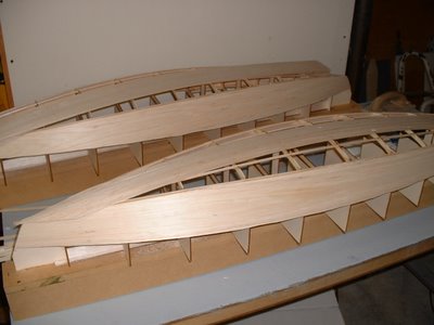
The first step was bending the forward end of the long battens into position by sawing a horizontal kerf back almost to the frame and then installing screw eyes and turnbuckles to pull them down into position. The kerf was sawn on the table saw before they were epoxied in place.


The fitting of the first bottom piece involved making some measurements to determine if I could start with a half sheet of plywood. The answer was "Yes, but not a perfect rectangle". I needed about 24 1/2" from center line of the keel to the widest part of the side. So I split the 4x8 sheet with a slight angular cut, 25" wide on one end and 23" on the other using my circular saw and 8 guide board. I positioned the sheet onto the bottom using the factory 90 degree corner straight edge along the centerline of the keel with enough length forward to make it to the tip of the stem. Three positioning screws were put in along the straight portion of the keel. Then screw blocks were started about midway down the side and put in every 3" to pull the bottom down into place. After several blocks were installed, a line could be traced underneath by bumping the panel down into position and marking the underneath side, however the most forward part could only be guessed at because the panel was too stiff to bend into position. Then it was removed, rough cut to shape, and reinstalled.


Then the forward part where it needed to be fit perfectly into a butt joint was marked for another rough cut. The marking was done by putting a heavy coat of purple crayola along the previously fit side edge and then bumping the bottom piece down into the crayola to leave a line marked on the underneath side of the bottom. The panel was removed again and trimmed with the circular saw to within about 1/16" of the crayola line. Back on the boat and the slow process of fitting the forward butt joint was done - inch by inch. My 1" rabbet plane was great for getting the fit pretty close. Files and a paint scraper were also used. As a part of the joint was fit (sitting on the panel would push it into place), another screw block was put in place to bring it home. As the fit progressed, screw blocks were also placed along the stem to bring this side of the panel along. The panel began to overlap the stem as it twisted into position and excess material was cut alway with a handsaw. Every bit of extra panel removed made the bending easier. After about 4 hours of trimming, sitting and fitting, it was in place.


Then all remaining screw hole placements were marked along the chine and keel, the panel removed and screw holes placements were marked for the battens. Countersunk screw holes were then drilled for the remaining chine and keel holes that would not be using screw blocks. Straight holes were drilled for the battens as machine screws would be used for these during glue up. This panel was then temporarily clamped in place upside down on the other side of the boat to make sure it would be a good starting point for the other side. It was. It was traced onto the other half of the plywood.


A coat of epoxy was spread on the underneath side of the panel and all mating surfaces on the framework were coated with epoxy. Then a batch of thickened epoxy was spread on the framework. The forward part of the long batten was un-turnbuckled, the kerf coated with thickened epoxy and then re-turnbuckled into submission. The panel was then placed on the boat, the locating screws put in place and all screw blocks reinstalled. After putting in a couple along the chine in the middle of the boat, I moved forward to the transition joint and ensured that it was all coming togther in the same location, secured a screw block and then filled in the rest moving forward towards the bow. Then remaining holes got silicon-brass screws along the keel and chine. Machine screws #6, 3/4" long were used to secure the battens. A 24" reversible squeeze clamp was converted to a pusher and used from underneath to push the battens up tight to the bottom prior to screwing.

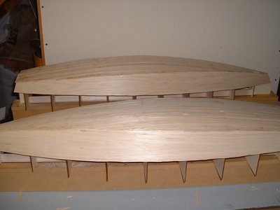
The next day, screw blocks were removed, countersunk holes drilled and 7/8" silicon-brass screws installed. The butt joint looked good with the largest gap being about 1/32". Excess epoxy was cleaned up and the forward part of the panel trimmed along the keel back to centerline or in the most forward part, cut and filed flush with the stem.


Back to the other panel with the traced line from the first panel. A bevel was hand planed on the panel edge where it would butt along the certerline of the keel to the previously installed panel. The bevel would provide a tight fit. Then it was rough cut, put on the boat and the whole fitting process began again. I thought it would be faster, but the keel centerline where the stem begins to curve also had to be precisely fit, and I think I was getting tired. It took forever, just like the first one. No clamps could be used on this one, so I had to make a few more screw blocks. It all came together nicely...epoxing in place would be another day.

The next evening, my friend Rick was recruited again and he dismantled the second bottom piece from the boat while I cleaned off my working table so we could put in screw holes and epoxy away. Rick is now a fully trained professional grade epoxy applicator guy so Ive got him ready for helping with fiberglassing the hull. This second bottom piece went in place nicely and a couple of beers were consumed in celebration.


The next part was the last two pieces to finish the bottom. The first step was to make the reinforcing butt pieces for the joint. Pieces of 1/4" plywood were ripped the approximate width to fit between the battens. Each piece is about 9" long. They were then fit, epoxied, clamped and screwed with about 4 each of #8 3/4" screws. Then the bottom piece was cut, fit, epoxied, screwed and clamped. Pretty simple compared to the rest of the bottom and side pieces.


Read More..

Free flat-bottom-boat building plans Guide

| 0 komentar |
Foto Results Free flat-bottom-boat building plans 1 Story 3 Bedroom House Plans Free Plywood Boat Plans Flat Bottom Boat Plans Flat Bottom Boat Plans Viking Dragon Ship Model
Read More..