Tampilkan postingan dengan label hull. Tampilkan semua postingan

IWC NYC The Half Hull on The Wall

| 0 komentar |


Any photos here are copyright their respective owners. Let me know and I will remove anything objectionable.

I apologize for obsessing. We have models all over the world and in some very special places, for example, The St. Francis Yacht Club in San Francisco or the one in Dubai. There is something about this setting and the quality of the surroundings that make this a particularly special place to have a model. It is in New York City in the place that people go to buy the finest things in the world. Indeed, IWC Schaffhausen is known for making some of the very finest watches in the world.

This is clearly an honor for us and its also been fun to see the parade of Champion Boxers, Fashion Models and Movie Stars who have had their photos taken in front of our "little boat" as they attended the Opening Gala of the brand new IWC Boutique at 535 Madison Avenue which was dedicated to the Great Muhammed Ali.

The whole thing started when we were approached with a rendering of a room and asked if we could make the model in the image - with a few modifications. The model in the image is a full-hull model and we would be making a half-hull and the backing panel that fits within the frame, but not the frame. We were asked to work up a proposal, not aware of who the customer was and received quick approval. As the project progressed, we learned more and more about what we were really getting into.

We then had to design the model according to the specifications of a design team in Switzerland. Our plans and samples of materials to be used were all submitted to New York, from where they were sent on to Switzerland for approval. The model needed to be relatively lightweight, but would clearly be much larger than most model boats of the class. It was to be of a particular raceboat that is a prominent contender in the Volvo Ocean Race, which is a grueling race around the world involving 70 sailboats that are as "state of the art" as anything currently made by human beings.

Unusual for us was that both the boat and the backing board had to be pure white. In fact, a color that is classified under the European RAL system of colors: RAL 9016 - Traffic White. It was unclear whether or not this kind of paint would be available to us, but we found an expert in European colors at the Annapolis Paint Store in Easton, Md. who was able to create both water-based and lacquer paints for the job.

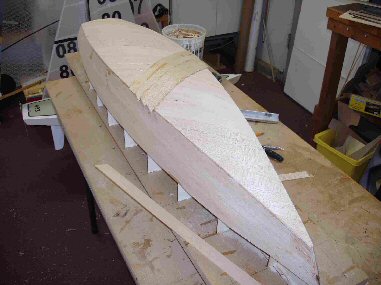
We were not able to procure drawings of the boat, so we used photogrammetry to develop the lines. You will find that they are quite accurate. The hull body was to be a little over 48" LOA (53" with bowsprit and radar arch). We decided to cut the hull from machinable foam, a material that is epoxy based with additional constituents to give it a density between pine and maple wood. It is preferable to machining wood because it is infinitely stable and there is no grain, which tends to cause print-through and does not take details as well. We have a small CNC machine that can cut a piece of material to a maximum length of 12". In order to cut the hull, we thought that we would have to farm the job out to someone with a much larger machine than ours.
We found that, for too many good reasons to elaborate on here, most CNC cutting companies did not want our job. Thus, we had to cut it ourselves with our small machine. This is actually good, because it allowed us to adhere to our rule of making every single part of the model ourselves.

We accomplished this by splitting the hull form into 3 two inch thick parts, divided along the buttock lines. The longest; the one closest to the centerline, required 5 operations in which an area was cut and then, using special alignment pins, the adjoining area was cut. In all, the hull body alone took 14 separate operations involving 64 hours of cutting. In order to keep the machine from binding an elaborate counterweight system was used. The hull could have been ruined at any stage for a variety of reasons, but we were able to keep problems under control. In order to reduce weight further, large holes were drilled into the hidden parts of the hull in much the same way as is done in the construction of aircraft parts. The 3 long parts were laminated with very slow epoxy and filled with a phenolic balloon/epoxy compound. When the surface was ready, it was finished with spray lacquer.

The mast and boom are steel. The majority of other parts are made from brass. The sails from rip-stop. Metal to metal connections were all made using hard silver solder.


From the deck to the top of the antenna at the masthead is 611", thus if you could stand on the deck, except for a very few people in the world, that point would be well over your head. The keel extends down from the hull by about 10 1/2". From the bottom of the hull to the top of the antenna is 82".

The backing board presented a different set of problems to overcome. In the interest of keeping weight down, it was decided to make the backing board from two 1/2" thick layers of Gatorfoam, a material that consists of a light foam core sandwiched between hard facings. The resulting one inch thick backing board might seem very sturdy until you understand that the panel is 54.73" wide by 121.65" tall or a little over 101" tall. Rigidity was enhanced by using cherry and baltic birch plywood in strategic locations so that they not only strengthen the backing board, but they strengthen the model structure and provide a hanging mechanism as well. Thus, the face of the backing board is only 1" proud of the wall.
Getting such a large piece from the Chesapeake Bay to 535 Madison Ave. looked like a logistical nightmare, but with over a week put into the creation of a very special container and good freight handlers, it made the trip in great shape.

We drove to New York with the models components and assembled it on-site, at times with the assitance of others working on their part of the Boutique. What the site looked like when we got there was very different from what is being shown all over the Internet in recent days, but we knew the kind of place that was being built. We left the store as a protective cover was being placed over our model.

Its hard to explain the feelings when one leaves a model like that. We dont know exactly when we will get to see it in its full glory, but were looking forward to our next trip to New York.

Take a trip to http://IWC.com and check out the forums forums for more...

Read More..

Star45 What is a hull Daves construction categories unofficial

| 0 komentar |
Model Sail Boat Building, How To Build A Wooden Star45 R/C Sailing Model: What is a hull ? and construction categories
A composite hull:
a hull constructed of wood and covered with reinforced plastic (cloth impregnated with resin).

OR:
a hull constructed using a laminate (sandwich) consisting of reinforced plastic (cloth impregnated with resin) on two sides of a core . Core materials may be foam or wood.
Read More..

Low powered planing hull lessons learnt

| 0 komentar |
Just before leaving on our recent road trip (4,500km), I wrote a post about a planing hull version of my popular Flint design. I was quite excited about the concept of a planing skiff for low-powered outboard, having had it in the back of my mind for a very long time.


With this latest design, (see here for details in the previous post), I had to produce the basic drawings in a very short space of time (about three days), as we were about to leave on what turned out to be more than four weeks of road travel. Having given thought to such a design in the past, I felt that I could get enough detail out to satisfy the owner/builder, who is an exceptionally capable person with high-level engineering qualifications.

Stitching-up Flint on which the new design is based
Here you can see the complex shapes which can be formed in plywood, as long as the panel shapes are "developable".
In order to produce a design which can be built stitch-and-glue from pre-computed plywood panels, one has to resort to relatively complex geometrical drawing. In the past, the drafting methods used to develop the panels tended to result in hulls which were full up forard and had straight buttock lines aft. The hulls so drawn are frequently apple-cheeked at the bow and lack displacement aft - not a good shape.

With the availability of complex hull modelling software, it is quite practical these days to engage in the design of developable hulls which were never possible in the past because of the unbelievable volume of calculation required in manual drafting. I am not a computer person, but I love my hull modelling and CAD software!

In my extreme rush to get drawings to the builder before leaving on our trip, I burnt the midnight oil fairing-up the hull shape on the computer, and when all was satisfactory, I hit the button to produce the panel developments.

Panel developments for one of my other designs
Off I went on four weeks of road travel, confident that the information provided would be adequate for my talented customer. The trouble is that in my confident state-of-mind I had neglected to test the developments as I usually do, using a scale model.

Scale model panel developments for Three Brothers, cut from 1/16" plywood

Testing panel developments at small scale
On the day of my return from the first of two long road trips conducted over the last four weeks, I received an email from my customer to say that he had cut all the panels for the planing hull version of of Flint (named Fleet) using his own CNC equipment (!), and that he was having problems with the initial stitching process. He was of the opinion that he was doing something wrong, having never built a stitch-and-glue boat, but I had a more sinister suspicion!

For a long time, Ive had a feeling that some hull modelling programs have a hard time doing developments which incorporate large amounts of twist and bend at the same time. When one considers the unbelievable number of calculations required, and the geometrical complication, it is little wonder. In order to test my supposition, I reverse-engineered the offsets of Fleet into Gregg Carlsons "Hull Designer" program, which had proven itself to be very accurate at this sort of job in the past.

I generated a set of developments using the Carlson Hull Designer, and superimposed them over the ones I had generated from the other program. In the illustration below, you can see the Carlson developments in red, overlying the others in a dark colour. The topside panels are virtually identical, but the bottom panels show substantial difference.

Fleet developments showing the originals in black, and the Carlson Hull Designer developments in red.
As you can see, there was enough difference between the two different bottom panel developments to produce serious problems. So, my customer had not caused the problem - it was caused by my over-confidence, haste, and lack of testing! Below are some photos showing the result...

Bottom panel having failed in tension at the keel-line near the first frame (near the bow)
View of the failure from the inside. See how the crack has initiated at the keel line, and extended upwards and outwards from the keel line.
Having wiped the egg from my face, and being confident that the new developments would solve the problem in subsequent boats (but I will be doing tests this time!), the problem remained about how to fix the first boat without having to scrap the entire pair of bottom panels. The suggestion I made was along the lines of, "if you cant beat them, join them". I recommended to the customer (luckily for me he is a very clever and resourseful chap) that he use a saw to cut a whole series of of similar "failures" across the keel line both forward and aft of the initial failure, so that the topside panels could pull the incorrectly shaped bottom panels into the proper position. This was done, and with each successive cut the original failure closed up a little more, and an even bend formed in the keel line.

Here you can see some of the deliberately cut lines, filled with thickened epoxy and finished off with a "stop drill" at the upper end.The dark line closest to the camera is a scarph joint, but you can see the artificial "failure" cuts filled with white thickened epoxy forward of the scarph.
Glass tapes dry-fitted, with some extra tapes to reinforce the new cuts 
A wider view, showing how the repair has restored the boat to a nice, fair shape.
There are a number of lessons from this project: -
  • I should not assume that drawings for a new design are correct without testing them;
  • Never give up, because just about anything can be fixed if you do some careful thinking;
  • Dont take what I say too seriously, as Ive proved myself to be wrong on frequent occasions!!!
Boat building  and designing is a lot of fun, and I really look forward to seeing how this particular boat turns out. I believe that there is a genuine need for an outboard-powered skiff which can perform well with a low-powered motor - say 4hp - and still be spirited and lively.
Read More..

Sheathing a Hull with Glass and Epoxy

| 0 komentar |
Over the years Ive discovered a number of building issues which people find intimidating, and one of those is the process of sheathing a hull with glass cloth and epoxy.

As with most things in small boat construction, glass sheathing is not difficult, but it must be done the correct way if one is to avoid a bad result. It is just as expensive and time consuming to do things the wrong way as it is to do it properly, so some research and preparation is time well spent! There many correct ways to do the job, but Im going to give you a very brief insight into the method which works for me. Because of space and time limitations, this is just the most basic demonstration. I hope it helps.

Prepare surfaces with longboard and other sanders. Round-over edges
Fill gaps with epoxy and sanding filler
Re-sand all surfaces with 80-grit paper to provide a good "tooth" for the epoxy, and thoruoghly vacuum the dust
Fill any minor blemishes and sand details
Drape hull with glass cloth and cut roughly to size
Tape overlaping areas and edges in place with a few pieces of masking tape
Smooth out cloth with a dry brush held at about 45 degrees to the surface
Trim overhanging edges with shears or scissors
Ready for epoxy
I did one side at a time on this job, so I peeled back one side and held it in place with lead weights
Mix up small batches of epoxy, pour on in sections, and spread with a squeegee held at a shallow angle. Dont press too hard, or the mix will become aerated. Just gently move it over the surface and allow a few minutes for the cloth to wet-out. Dont worry about an even finish yet - just distribute the resin and allow the wetting-out to proceed on its own.
Attend to details such as the dry edges with a disposable brush
Continue working downwards until the whole section is completely wet-out. There is no rush, as long as you continue working out from a wet edge.
When completely wet-out, remove excess resin using a squeegee initially, and then finish off with a dry foam roller. The aim is to remove all liquid resin from the surface, leaving just the wet cloth with no puddles
The result should look like this - an even, textured surface with no pools of liquid resin. The glass cloth should be in direct contact with the timber, and not be floating in puddles anywhere.
Another good example of a proper finish after the initial wetting-out coat.
After the first coat has cured to the point where it has stuck the glass to the surface, but before it has fully cured, a second coat can be rolled or brushed on to fill the weave of the cloth. This is usually followed by a third coat a few hours later. In this photo you can see how the weave of the cloth has disappeared.
Here is the hull at a later stage after the hull has been sanded. Because of the fill coats, and the smooth application process, the sanding was done without cutting into the cloth - just the fill coats of epoxy were sanded.
For bigger jobs, extra hands are required to get things done before the epoxy goes off. On this 22ft hull, we had my wife, the owner/builder, and myself all working in a team
The result speaks for itself
Read More..

star 45 construction double diagonal planked hull

| 0 komentar |
Model Sail Boat Building, How To Build A Wooden Star45 R/C Sailing Model
star 45 construction | double diagonal planked hull
From: "John Fisher"

Here are some photos of Sherwood Jones Star 45 with double diagonal bottom planking. He used two layers of 1/16 planking. The planks are 1" wide. He then covered it with 1 ½oz glass. Weight is about the same as mine with the 1/16 longitudinal planks and two layers of 3.2 oz glass. Just goes to show that there are multiple ways to solve a problem.
John
Read More..

Fleet a Planing Hull Version of Flint

| 0 komentar |
Back in about 2003 I was asked to design a rowing/small outboard boat for operations in a short, steep chop, with the emphasis on lack of pounding. The resulting boat, named Flint, has been very successful and popular. She is very easy to build - if you follow the assembly sequence - and a distictive feature of her hull is the fine, hollow sections in the forward part of the boat. What is amazing is that this shape can be produced from a single developed plywood panel. I have tried to achieve this sort of shape in the past using conventional projection of developable panels, but the geometry required to produce a hollow shape has always defeated me. The arrival of computer programs which have the ability to do the mathematics saved me from myself!

Proof that the hollow sections come from a single panel of plywood
The very first Flint, built by Eddie Guy
In recent times I have been approached by a number of people who have wanted to build a planing version of Flint. The hull of the original rowing/sailing/small outboard version is of the displacement type, although her fine sections and high length-to-breadth ratio mean that she can be pushed faster than her theoetical displacement speed which is 5 knots. On launching day we got her to 6.1 knots with two adults and two teenagers onboard, using a 2hp Yamaha at part throttle. Steve Dorrington got his to a speed of 6.2 knots under the urge of British Seagull 40-plus - certainly an achievement!

Steve Dorrington measuring his 6.2 Seagull-knots using a GPS. Note how Steve has to sit on the midships thwart in order to retain proper trim. In the case of the planing version, a helms-person should be able to sit aft and operate the outboard without a tiller extension.
Bruce Erney, on the east coast of the USA modified his Flint to take a 6hp motor and got her up to 17 knots, I think, but he needed to put trim tabs on to overcome the tendency of the displacement hull to point her bow at the sky. I was concerned about the exercise, but Bruce had many successful trips while fishing in the big waters.

Bruce Erneys trim-tabs

One of Bruces many fishing trips in his modified Flint

Ive made a number of attempts at drawing a planing version of Flint and things were brought to a head this week when a friend/customer for whom I have great respect, asked me for a semi-disposable planing power boat which he and a friend could build over a weekend or two, to be powered by a 5hp outboard. He looked at few drawings I had on hand, and chose a preliminary sketch of a planing version of Flint, which I drew as a discussion piece for Rick Hayhoe a number of months ago.

Lines Drawing of the original Flint
Lines drawing of the planing version, now called Fleet
In the above drawings you can see the substantial changes made to the shape of the hull aft of the midsection. I have retained the fine, hollow forward sections, although Ive increased the rake of the stem very slightly in order to reduce the severity of the bending and twisting of the plywood panels. With good-quality ply the hull is easy to assemble, but some people still insist on using poor-quality sheets in order to save a dollar, and end up encountering problems - hence the alteration.

My aim with this design is to retain the extemely light and simple style of hull as seen with the original Flint, and to have her run efficiently with nothing larger than a 4hp motor. This is important in my part of the world because we can operate with up to, and including, 4hp without needing to register the boat. The customer wants to use a 5hp, and specifically asked for a water-shedding foredeck and side decks under which he can store fishing gear. He intends taking her into the open Pacific off the Queensland coast here in Australia, and so adequate emergency floatation is essential. His boat will have built-in buoyancy under the sternsheets (aft seating which extends aft in a horseshoe arrangement),  under the midships thwart, and under the large foredeck. We have not finalised details of the arrangement, but here is a very preliminary sketch with the decks and seating shown in blue.

Here is a very sketchy drawing showing one idea of an internal layout. The final version is a fair way off yet, I think. The decks have very pronounced camber to aid in water shedding (those odd looking bits at the bottom are just working drawings to establish the height of the inner edges of the side decks at each station). Note how the cambered foredeck makes the sheer look much flatter than in the undecked original - this is an optical illusion. 
This little article should give some indication of just how much the character of a boat must be changed when the mode of operation is altered. However, a completely open version with a very small motor may retain the spartan feel of the original, while still performing in the semi-planing and planing modes. When the plans are complete and the boat tested, Ill post more details. For those who want to read more about the original Flint follow this link and this link.


Read More..