Tampilkan postingan dengan label comments. Tampilkan semua postingan

Answers to a couple of recent comments

| 0 komentar |
Here is comment received regarding Fleet:-

How much does she weigh?
What I like about flint is that the center of balance is over the center thwart making her easy to carry and light enough for this senior citizen to car top.


Well, I cant tell you how much she weighs because we havent weighed her yet, but the material thickness is the same as on Flint and the area of plywood is only 8.4% higher, indicating an 8.4% weight increase.  The Fleet shown in the pictures has a foredeck and inwales, but the standard Flint and Fleet have tank-tops on the foreward and aft buoyancy tanks, so it probably all evens out.

Based on just the plywood in the bare hull, the weight of Flint panels is 24kg(53lbs) and in Fleet the same is 26kg(57lbs). The centre-of-gravity of the hull panels (including transom without framing) is at 1.96metres forward of the aft perpendicular i.e. at the midships thwart near the aft edge.

The weight of any boat depends tremendously on the density of the materials used, and the attitude of the builder.
________________________________________________________________
In relation to my recent post on the virtues of the sprit rig with the jib set flying, Dennis Marshall writes: -

May I ask what the line is hanging from the peak of the sail?

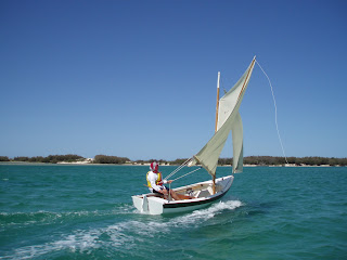
Dennis is asking about the light line which can be seen in a number of photos, running down from the head of the sail at the peak end of the sprit

The light line is just visible in this photo
The line is a vang. I suggested that it be used in certain conditions when hard on the wind and when running free, to control the amount of twist in the sail, and (when running) to prevent the head of the sail from moving forward of the beam i.e. forward of a a line drawn at right angles to the centreline of the boat. If a sail moves forward of the beam, it is a sure invitation to a Death Roll.

The light line is run from the head of the sail near the peak of the sprit down to a thumb-cleat on the weather quarter and then to a little fairlead on the rudder head and then along the tiller to a small V-jamb cleat within easy reach of the helmsperson. When tacking or jibing, the line is flicked off the thumb-cleat and quickly moved to the one on the new weather quarter.  It only requires a light tension on the line (vang) to haul the head of the sail in to reduce twist in the sail.
Read More..

Answers to a few comments

| 0 komentar |
I apologise for not having replied to the last few comments, but Ive been snowed under with other duties and this is my first opportunity: -

Rossco, Did Ross Trinder use 4mm or 6mm ply on his longer Water Rat? With my 9 Water Rat I used 4mm with a full length centre stiffener of 1/4" x 4" western red cedar ( from an old verical blind) plus some smaller ply pieces and a pair of heel pegs, between the centre stiffener & the chine.You can see these in the photos I put up in Duckworks Magazine forum under "Water Rat".The bottom seems quite stiff enough with these, plus of course,the fore & aft facing seat mounting cleats. My Water Rat weighs only 17kg,which is very light,so using 6mm will probably increase it to about 25kg which is still very portable. Would "rowerwet" be better advised to use 6mm if he intends surfing his boat? Al Burke
Ross Trinder used 6mm ply on his long version of Water Rat and she turned out to be about 28kg (62lbs) which is quite heavy. However, he said that he used locally-sourced "Pink" BS1088 ply. In Australia "pink" ply normally means Pacific Maple (Meranti) or a Malaysian hardwood like Keruing all of which are quite heavy. If built from 6mm Gaboon (Ochume) the plywood weight of all of the panels in a 10.8 ft Water Rat should weigh 10.5 kg (23 lbs). Ill leave it up to your judgement to work out how much the timber, glass, and epoxy would weigh.
As Al Burke points out, the boat can be made from 4mm material, but stiffeners will be required in strategic locations. The stiffness of a panel increases (and decreases by the cube of the thickness, so 6mm ply which is supported around all edges is 3.375 times the stiffness of the same panel in 6mm!
 Here is another one from my mate, Al: -

Rossco, By way of a general comment on both First Mate & Phoenix3,I have been impressed with the speed Paul Hernes achieves in the videos of him sailing in a stiff breeze & the ease with which he handles the boat.I know the sensation of speed appears greater when close to the water,but he is ceratainly clipping along. My question is:- are both designs able to break out & plane? Al Burke
Yes, Phoenix III can break out and plane. In the following photos you can see John Shrapnel sailing Paul Hernes boat on a good day with a deep reef tied in the mainsail. This is a good demonstration that traditional rigs can drive a boat fast! I havent had direct experience with First Mate yet, but Id expect her to be as good or better due to being wider at the rail and easier to hold down. Both boats have substantial rocker, so they sit bow-high when planing, but the result is not extreme.


From Shaun come two nice comments: -

Your photos and step by step explanations are a huge selling point for me. They keep bringing me back to the blog. Not only are you highlighting your designs but are show casing the workmanship that goes into turning out a beautiful boat. I am hoping to make my first build a Flint with sails. I started a bit backward and have built some spoon oars first to get the hang of epoxy. Cheers, Shaun
Nicely done photos and commentary, makes me believe I could replicate the process. I am interested in trying some birds mouth oars. Do you include such plans with your Flint design? Cheers, Shaun

Shaun has said that he has started backwards by building oars first, in order to gain experience with epoxy. I think this is an excellent approach for an inexperienced builder and I encourage the method. The other thing to do is to build a very small tender of simple canoe so as to get the hang of the processes. In my First Mate plans I include patterns for a simple galley box which is made as a mini-stitch-and-glue project.

No, Shaun, there are no Birds Mouth spar plans for Flint, as the spars are so short and slender that the weigh saving does not justify the trouble. In fact, the spars for Flint are parallel-sided and can easily be made out of a wide variety of materials including alloy tube and carbonfibre tube. Id make them from timber - it feels nicer to the touch.


Im currently finishing off the Whimbrel plans, but due to workload the process will take about another month, I think. I like the boat very much indeed, and she should be a simple project for someone who has some experience.


Read More..

Responding to some comments

| 0 komentar |
Firstly, a note from my friend, Allan Burke,another from a contributor in Florida, and one from Woody: -

"Rossco, Just knew this design was coming! Ever since I read Munroes story something keeps stiring inside me about Egret. WHEN I win the lottery you can build US an Egret original,then well both know how she sailed. Meantime your new design on the same theme will whet many other appetites Im sure. There will be much interest in this boat of yours from those who know Egret. Al."

"Something about Egret grabs the soul! Living in coastal florida makes it even closer to home. Anxiuosly awaiting updates, as this design is closer to reality for me than the 28 replica!"

"Lovely! I wonder if the final drawling will be made for the possibility of the occasional night sleeping aboard. Woody"


Well, the customer who prompted the design of this boat has commenced purchasing materials and I hope that we may see some progress in a month or so. I dont think it will be a quick build due to his current workload, but the hull will be easy to put together once the components are assembled.

Construction is from 12mm, 9mm and 6mm marine ply using the traditional skiff construction technique of wrapping pre-cut side panels around frames and bulkheads i.e. no strongback is required. The bottom panel (12mm/1/2" ply) is fitted inside the topside panels flush with their lower edges, and then set in position with glass/epoxy as in stitch-and-glue.

As I mentioned in the original post , this design is not a copy of Egrets lines, but is an attempt to capture her character. The proportions are significantly different, as a direct copy would have resulted in some elements being unsuitable due to the difference in physical size. When drawing the new boat, I did not once refer to the Egret drawings until after I was completely finished.

As for sleeping aboard, there is just enough width to have a person sleeping on the floorboards on either side of the centreboard case. Length is not a problem.

Im very interested to see how this boat goes. She has a small sailplan, but I suspect that she will go much better than many people would expect, and the customer visualises himself poling over the flats in good weather.
_________________________________________________________?

"Love Phoenix III and First Mate. Your post prompted me to pull down L Francis "Sensible Cruising Designs", and the beach cruiser was in the book. Great inspiration. Another of his designs that would make a useful beach cruiser is "Carpenter", built lightly..."

L. Francis Herreshoffs Carpenter - 18 LOA 163"LWL 46" Beam
From Sensible Cruising Designs - International Marine Publishing, Camden, Maine
Ive always been fascinated by the shape and size of Carpenter, and in many ways she would perform the same function as Little Egret. But in my mind, I see Carpenter sailing on blue water off a rugged coast - comfortable under her modest sailplan and with her able and sea-kindly hull giving her skipper confidence....
_______________________________________________________________________

"Great post here in regards to stainless steel fasteners , my dad runs a company that produces them back in the UK, ive always been interested in their applications."

I dont use stainless steel fasteners very much because I am concerned about crevice corrosion. Stainless steel is ok as long as it is 316-grade, and is exposed to a free flow of water or air. But if the flow of air or water is restricted, rust forms quickly. A good example is the common sight of a stainless steel chain plate bolted against the topsides of a boat - the outer surface of the chain plate looks shiny and perfect, but there is a long red rust stain running down the boat where the chain plate is bolted against the hull. If you must use stainless steel, make sure it is 316-grade, and also be absolutely certain to set it in good-quality polyurethane bedding compound.

For permanent screws and nails, I use silicon bronze, but I do make extensive use of 316-grade stainless steel screws and brads for temporary fastening. People ask me why I use stainless if the fastenings are going to come out anyway? The answer is that if one breaks off, at least there is some chance that it will resist corrosion if it is burried in epoxy.
_______________________________________________________________

"Curious as to what design is "waiting in the wings" that may use leeboards. Sounds interesting. Maybe its the one that will balance with a passenger seated on the aft thwart? Woody"


Well, there is the hull I was talking about. She is the same sort of size as Phoenix III and First Mate, but built either as a strip planked hull, or as a glued-lapstrake (clinker) hull with eight planks per side. The transom is shown vertical, but in the finished drawings it will have 10 degrees of rake. Breadth at the rail has been carried forward so as to allow adequate spread at the oarlocks when rowing from a forward position (yes, Woody, you were correct) and to provide reserve buoyancy. The other reason for carrying the breadth forward is to allow for better mounting of leeboards if that was considered.

These plans wont be available for quite some time, as I am too busy with building work, but I would like to build one for my own use - maybe....
___________________________________________________________________________?


Read More..

Whimbrel Yet Again Two Comments

| 0 komentar |

Robert has followed-up on the previous couple of comments: -
Ross, since you see the utility inherent in the slot-top option and go so far as to state you would thus modify Whimbrel for your own use, would it be feasible to offer an additional sheet in the plans to make this an option?

Then there is that magic number I was waiting to see... the hull weight. I know more than one person is eyeing Whimbrel as a possible Everglades Challenge option. I do hope the actual number is "significantly reduced" as you believe. The Core Sound 20 finishes out at between 500 and 600 pounds sans gear, no cabin of course. Time will tell...

Well, I have to admit that I havent done a full "weights and moments" calculation on Whimbrel. What I did in the previous post (with full disclosure at the time) was to take the total volume of plywood in the boat, multiply the volume by 600 to determine the weight of the ply in kilograms, and then I simply doubled it to account for timber components, glass, epoxy, fasteners, rig etc. This is totally unscientific, but I believed it to be conservative. What is more the selection of 600 kg/cu.m was also conservative, as we are able to obtain good quality marine plywood here which has an actual density of 420 kg/cu.m. The reason that I used 600 kg/cu.m as the figure was to account for the variability in the actual weight density of plywood supplied by the retailers. There is a retailer in this country selling BS1088 plywood which is advertised as being 430kg/cu.m - but when tests were conducted locally on actual samples, the density proved to be around 600 kg/cu.m!!!
If one was sure of having 420kg/cu.m ply, and even using the conservative doubling system that I described, the weight of the boat (including decks and cabin) could be as low as 220kg/484lbs.
Im sure that the Core Sound 20 is an excellent boat, but she is a different vessel from Whimbrel. Firstly, Whimbrel has a full cabin, lots of built-in compartments, a self-draining cockpit, and a tabernacle. In addition, I designed Whimbrel to comply with the scantlings rules as laid down by Dave Gerr N.A. who is currently the Principal of Westlawn. as far as I can make out from my own study and from discussions Ive had with a well credentialed Westlawn graduate, Dave Gerrs scanting rules are conservative in comparison with ABS standards - in other words, if you build to Daves rules, the boat will be stronger and slightly heavier than required. I am very happy with that!
One of the things I had in mind when I drew Whimbrel was that I wanted a solid little ship which would last a lifetime. As you are probably aware, I hold the work of Phil Bolger in very high regard, but I was mildly concerned to discover that a Micro built to specification was somewhat flimsy. For example, you can push the side panels in and out, and when walking around on the cabin top it is necessary to place feet near frames, bulkheads or other supported areas, because the 6mm/1/4" plywood (from which the entire hull is made) flexes alarmingly.

Whimbrel has 12mm/1/2" panels on the bottom, 9mm/3/8" ply on the topsides, 12mm/1/2" on the cockpit floor, cockpit seats and cabin sole, and the cabin top is made of 6mm/1/4" on 50mm x 20mm (2" x 3/4") longitudinal stringers on 200mm spacings or less. This is a rugged "tugboat-tough" boat and not a light-weight daysailer.

Yes, I will do a sheet covering the simple option of a "slot-top". One could easily stand against the forward end of the cabin and reach down into the anchor locker and deck hatch.

Rick Hayhoe has written back: -

<> <><>
I went back over images I have and could access of scows among American watercraft, where they were used in the Gulf of Mexico fishery and for transport of timber, coal and other bulk cargo along the US west coast. I find, contrary to the opinion I expressed earlier regarding Whimbrel, that most or all of them have the bow transom terminating at or near the waterline. They were, of course, coastal and inshore craft, but they still would have met severe conditions at times. However, all of those were much larger vessels than Whimbrel, with displacement in the tens and hundreds of tons, with vastly more inertia in meeting chop or steep waves, able to punch through any but the biggest waves but hopefully able, while plying their trade of coasting, river transport or inshore fishing, to make shelter before such severe conditions arose. Their hullforms, like Whimbrel, were determined by their function, with priority over seakeeping, often for the benefit of operating in shallow water, taking the ground at low tide and carrying large volumes of deck cargo. In a boat the size of Whimbrel I would still find it safer to follow the design habits of one of the peoples with a long tradition of scow bowed small craft, either the Scandinavians, who invariably got their open water round bottomed prams profile and buttock lines well up out of the water before they terminated them in bow boards, or the Asians, who on smaller craft either rolled the bow boards back to a very low angle of attack, like a garvey but much narrower, or built them with narrow stems flaring into transoms well above the waterline, or some of each. Still, I want to make it clear that I admire Rosss Whimbrel design, have since I first saw it, and I understand how the original clients parameters resulted in the outcome. The boat is meant to be used as a camp cruiser, not a passagemaker, so the design is defensible as Ross puts it. That said, Id still make what I consider better use of scarphed whole and half-sheet lengths of marine ply and make its shout a bit longer, thus narrowing and raising it, while keeping all else the same. His rig, accommodation and use of leeboards are a winning combination on such a small craft, and the accommodation and applicability of leeboards are both facilitated by the scow bowed hullform. Its a very neat solution to a nettlesome set of design parameters, which I like a whole hell of a lot better than solutions to similar parameters by some others who shall remain unnamed.
Rick Hayhoe
I thank Rick for his comments, and given that I have already responded to his initial comment, and because Rick has written so well in his second piece, I dont feel the need to reply further. However, I hold Ricks opinion in high regard, and I have therefore been moved to continue with hull modelling experiments with longer hulls which carry their transoms higher and less wide. Unfortunately, my time is so limited (it is the old One-Man Band thing again - Im trying to be a boatbuilder, a designer, a blogger, an email respondent, a magazine writer, and a retailer of components all by myself - I just cant get it all done, Im afraid), that the initial modelling attempts need more time devoted to the detail.
Read More..

Fiberglassing information and comments

| 0 komentar |
Polyester resins are formulated in many make ups. To change the liquid resin to a solid you must add a hardener to catalyze the mixture. Whenever resin is referred to in this manual it is intended that it be properly catalyzed before use. The resin you choose for your model should be pre-accelerated. This resin will commonly have a purplish hue in the liquid stage and may change color to indicate states of cure. Resins should be at room temperature (60°-90°F. ) for curing. Among the polyester resins `available are the air, inhibited types. Lay up, spray, and gel-coat resins are formulated so their surfaces will not cure readily while exposed to air. This is advantageous if several layers of glass are to be laminated over a period of time. However, it may present a problem to the unsuspecting buildr who finds the surface of his resin "forever tacky". Sometimes, applying a layer of hard .bowling, alley wax will solve this problem. Gel- coat resins therefore, are not used as a finish coating on completed boats because they are air-inhibited.

Finishing resin or hand-lay-up resin is commonly a waxed resin. When special waxes are formulated in the resin they will move to the surface as the resin cures. This is an advantage if this is the outer surface. If you want to bond to: this, surface you must first sand it thoroughly and then " prepare, the surface with acetone or polyester solvent.

Polyester resins may be thinned with acetone and styrene. The common polyester hardener is methyl ethyl kettle peroxide (MEK60). -Resin and hardener must be handled most carefully and in strict accordance with the manufacturers -instructions. The amount of hardener or activator in conjunction `with the room or ambient temperature determines the jel time and the cure rate of the resin. The jel time is the period that the resin remains liquid until it turns to a jelly just before curing hard. Resin has a "pot life" and is only workable for the time before it jels; this may vary from seconds to several minutes. CAUTION-DO NOT use too much hardener. Styrene will thin the resin and become chemically part of the cured resin. Acetone will thin the resin but will evaporate during cure. Acetone will change the characteristics of the cured resin and may result in brittleness and other unwanted characteristics.

Polyesters may be filled with a number of components from sawdust to pecan shells. Most common fillers are Cabosil and micro-balloons and macro-balloons. This filling may make the resin thixotropic and filled resin may vary from a slurry to a heavy paste. Macro-balloons and micro-balloons are used to make a foam-like putty that will work as a flotation foam.

Polyester will bond nicely to polyester. We stress that surfaces must always. be cleaned and prepared for bonding. The bond between two fiberglass parts, such as keel and shell or hull and deck, will be enhanced if the interface between bonded surfaces is filled with a layer of saturated matt, cloth, or filled resin. Polyester resin is frequently used to bond to wood as a glue. However among wood glues, polyester rates poor. The initial bond to wood may look all right but it has a history of delaminating. We will not rule out its use for model building. However, there are better wood glues and the best of the waterproof glues are better, many epoxies.

Fiberglass is not at its best under tension. Spread or distribute any tension . load over a wide area. The same goes for compression loads that should be spread out also. This fiberglass found in models will tear if pulled on so always spread the load - more on this later.

You must remove all waxes in order to bond to fiberglass and you can reverse this and coat surfaces with hard floor waxes during building to protect surfaces from accidental spills. Also remember to use only resin-resistant tape such as Scotch brand Cellophane tape which is inert to resins; regular masking tape may be used if not in contact with resin or solvents.

Fiberglass has the outstanding feature that when molded in curves it has very high strength imparted to the part because of the curves. On smaller models the curves of the hull provide sufficient strength for the model. On larger models you will need stiffeners. These may be ribs or bulkheads which add support to the hull. These can be of the aircraft framework type. Another stiffening method is to make a sandwich. Here the strength of the GRP is achieved by laminating a light weight core between two layers of fiberglass.

From: "Mitch Martin" 2006 August 1

Working with WEST is similar to polyester resin, but it is stronger, doesnt smell bad, and hardeners can be selected for your application. For example if I was mixing the epoxy for glassing a hull that would eventially be painted I would select the extra-slow hardener 209 which has a pot life of 45 minutes. Thats much longer than a polyester resin pot life. The down side is the cost, its pretty pricy stuff. Another trick is to mix in the graphite powder and it gives the finish a carbon fiber look.

from John 2006 August 1

The pot life with the 105/209 is 40 min or so. I have used that
combination when doing vac bagging and it allowed plenty of time to wet
out the fabric on a 60" boat, then apply mastic, then the bagging
materials, then pull the air out. I have also done 72" long 10Rs and had
no issues with the pot life. Now I am usually about 70 deg, so that slows
it down some too.

Now the 105/205 can be more in the 10 to 20 min range depending on temp.
Also how deep the container is that you mix the epoxy will influence the
cure time. Deeper is faster.

Billie Geislers comments regarding Epoxy:

I use strips of cardboard scissored from breakfast ceral boxes for mixing and applying the epoxy. I use aluminum beer cans for containers. I cut the bottoms off about an inch up the can with a curved exacto knife. I find that I can get a pretty good mix of resin to hardener by cutting the mixer cardboard the same size, then use them to measure the epoxy and hardener.

I dip the cardboard mixer stick into the resin and scrape off all that will remain on the stick, after I wind up the strings, into the beercan. Then I use another fresh cardboard mixer stick, and dip it into the hardener to the same depth as I dipped the first stick into the resin. I let it drip once before I scrape it into the beer can. The difference in viscosity seems to get the ratio about right, even though it seems that no way is the little bit of hardener that stays on the dipper is going to be enough to work. The cardboard mixer sticks are inserted vertically into the resin and hardener, and scraped on the edge of the beer can.

You can pretty accurately go from a hot mix to a slow mix by simply varying the depth of the mixer stick in the hardener. It works on very small amounts, and about two dips from a half inch wide cardboard mixer stick will be enough for a plank on each side.

I use small jars to contain the epoxy components that I am working with, and label both the jar and the matching lid as resin or hardener. That way, if I happen to dip the used hardener dipper into the resin, or mix up the lids, I dont loose my whole supply. I like horshradish jars from Kraft.

Experiment with your epoxy before smearing it on your hull, as my epoxy is about 20 years old and the ratio of hardener to resin may work differently with yours. Just vary the depth of the hardener dip relative to the depth of the resin dip, until it works for you. It doesnt take long to learn to mix very small amounts with reliable cure results.
Read More..

Catching Up on Some Comments

| 0 komentar |
For quite a long time now Ive been unable to up-load photos to my blog without going through the process of putting them on a picture hosting site and them using the url of each individual photo. With the combination of Christmas/New Year, and a lot of building work to be done, I am afraid that posting has fallen behind. This is all done in my own time, and at my own expense, and it sometimes must take second place to paying work!

The computer people here will roll their eyes, but Ive finally discovered that the picture loading problem was caused by incompatibility between the Microsoft Internet Explorer I had been using and the Google Blogger program which I use for the blog. Ive now changed to Google Chrome for my internet work, and all seems to be working fine.

So Im going to start off by answering a few comments that have been left on some of my posts.

Mr.Lillistone,Ive followed your blog for a while,Thank you for your time,energy ,and expertise,It is appreciated by many!!! I know you have built both Michalaks Mayfly and Redmonds Bluegill,Im considering building either one and would like your professional opinion.Do you think the Mayfly leeboard and balanced lug sail plan could be used on the Bluegill ,if the sail is properly positioned over the leeboard,and leeboard is centered on beam?I would like the open cockpit the leeboard affords.Any info. Would be appreciated thanks in advance ! Jerry Fehn on Reality

The Bluegill we built, showing her centreboard case
Jerrys comment refers to a matter which has nagged at me for many decades. A centreboard is convenient to use and is to a large extent self-tending i.e. put it down and if you are too busy for detail work, just leave it down until it hits the bottom coming home. On the other hand, leeboards need to be handled from tack to tack because, as their name suggests, they only work when set on the leeward side of the boat.

A raised leeboard on a Dutch Yacht (taken from http://www.leeboards.com/)
That is me sailing my Bolger Nymph a long time ago. I had fitted her with leeboard for experimental purposes, but in this photo they are both raised as the boat is running downwind.
My understanding is that leeboards originated in China, along with such things as stern-mounted rudders, centreboards, and watertight bulkheads to name just a few Chinese nautical inventions/developments. Leeboard use has been widespread, but most people associate them with Dutch, German, and British sailing vessels.

This shows a typical lowed position for a leeboard.

Leeboards may appear untidy to some eyes, and to need handling from tack to tack, but they are highly efficient. Frequently the boards are angled away from the hull to allow a clean passage of water between the hull and the board so as to prevent excessive drag. This feature also means that as the boat heels, the board becomes more and more vertical - which is just the opposite of what happens with a centreboard or fixed keel. Not only does the board become more vertical, but it also works from the surface of the water, whereas the centreboard only works from where it exits the bottom of the boat. This has the additional benefit of allowing leeboards to operate effectively in a partially raised position in shallow water, and not extend below the bottom of the boat.

A Bolger Black Skimmer sailing with her board partially raised. The board is effective, but does not extend any deeper than the hull, if at all. (Photo from Woodenboat Magazine)
An overlooked plus with leeboards is that because they each operate operate on different sides of the boat (in their normal form anyway - more on that later) the sectional shape of the boards can be asymmetrical, allowing the board to lift the boat to windward at a reduced angle-of-attack in comparison with a board which has a symmetrical foil shape. The boards should have a flat face away from the boat and a cambered face towards the boat.


An Otter II with both of her leeboards raised while on her shallow water mooring. Note how the owner has the leeboards on the incorrect sides. The cambered section should face the hull, so in this case the starboard board is mounted on the port side, and the port board is mounted on the starboard side!
You may wonder why leeboards frequently have a tear-drop or triangular shape, with the widest part down low. This is because they are surface-piercing foils, and the inverted taper shape helps to reduce air-ingestion  on the low-pressure side of the board.

Despite the visual and actual clutter of the boards, they have some potent advantages in addition to the ones already mentioned: -

  • the interior of the boat is totally free of the intrusion of a centreboard case; and
  • the bottom of the boat is stronger without a centreboard slot; and
  • there is no centreboard slot to get jambed up with mud, stones, shell grit and sand - which therefore leads to the centreboard being jambed.
It is possible to mount the leeboard to one side of the boat only, but for that to be effective, the board must be prevented from bending away from the side of the hull when it is on the up-wind side. This can be done using a dagger leeboard ( which I guess would be a weatherboard on one tack) where a variety of methods are used to hold the board in place. Alternatively, you can have a pivoting lee board as developed by Jim Michalak and others. In this case, the board is held parallel to the side of the boat by a pivot bolt and wooden guards and/or slots, but the board is free to pivot in the vertical plane. Although simple in concept, great care is required to ensure that all of the pivot locations and guard angles are absolutely correct.


Above two photos show the Michalak Mayfly 14 pivoting leeboard
Here is the finished boat
Note the completely unobstructed interior....
...the very simple raising and lowering gear...
...and the lower guard with the pivot bolt going through (the piece of unpainted wood is positioning piece on the trailer)
Now, to finally get to Jerry Fehns question - Yes, it would be possible to mount a pivoting leeboard on Bluegill in place of the centreboard and case, but great care needs to be taken with the positioning of the board relative to the centre-of-area of the sail, and also with the geometry of the pivot point and the guards so that the board remains parallel with the centreline of the boat.

Having said all that, the first person who should be consulted would be Steve Redmond, the designer of Bluegill. As has been said many times in the past, no-one should alter the design of a boat without getting input from the original designer. This is not grandstanding at all - it is simply that the designer should have put a lot of thought into the design, and there may be elements there which are not obvious to the casual observer.

My recommendation would be to build something like Mayfly 14 if sailing is the most important aspect of operation. She sails superbly in my experience, and the shape of the hull is optimised for sailing whereas Bluegills hull is a deliberate attempt to produce a hull that will row, sail, and operate as a planing powerboat.
Read More..